My mechanisms final is complete. Instead of using an LED source, I was given a broken samsung pocket projector and decided to use it as a source. How many tabletop moving pocket projectors are there? The projector made a great addition to the project.
First I needed to fix it. The input source connector had ripped off the mainboard, taking with it a few traces. Even if it had been a clean break, finding the weird custom connector was not going to happen – let alone finding the cable itself. I decided to just google the two IC’s closest to the input connector – assuming they were the analog/digital converters.
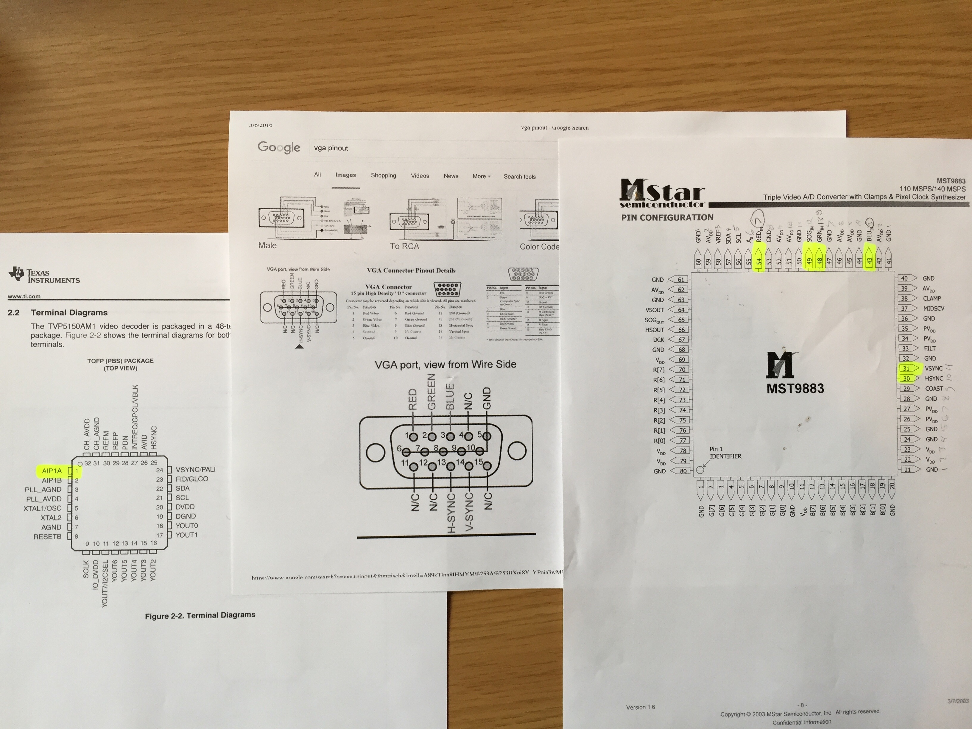
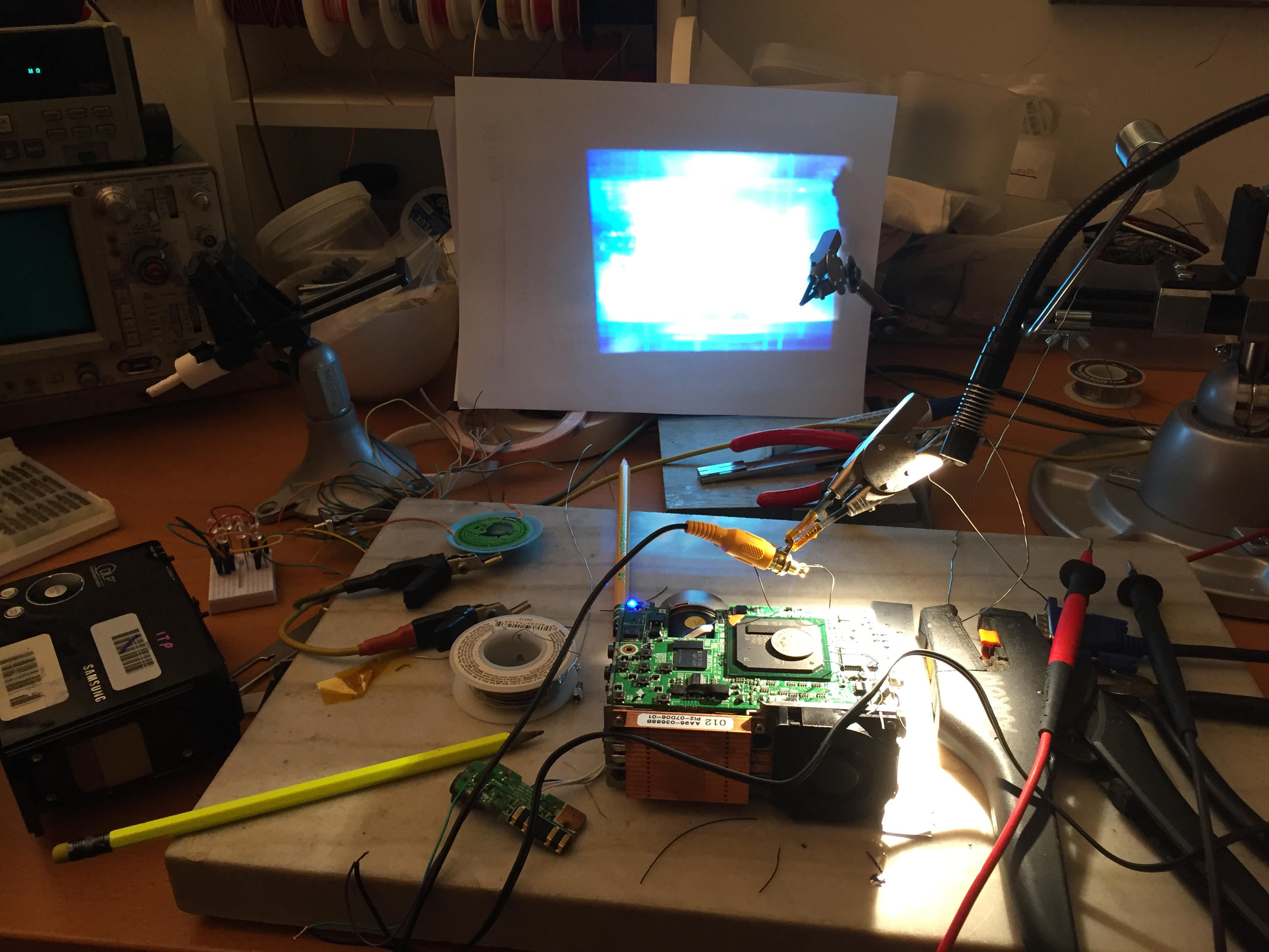
One was the VGA converter, the second was the analog composite video DAC:

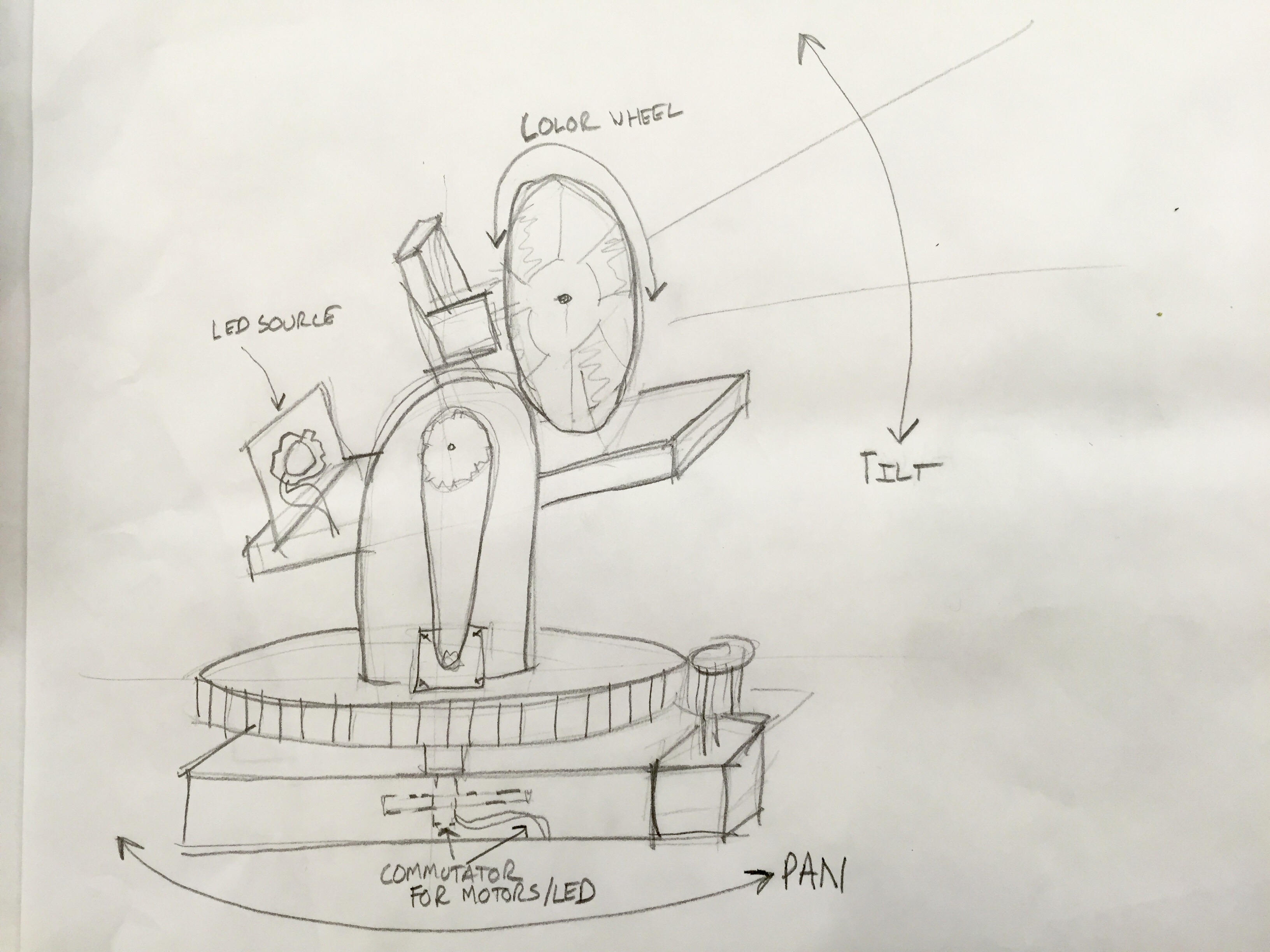
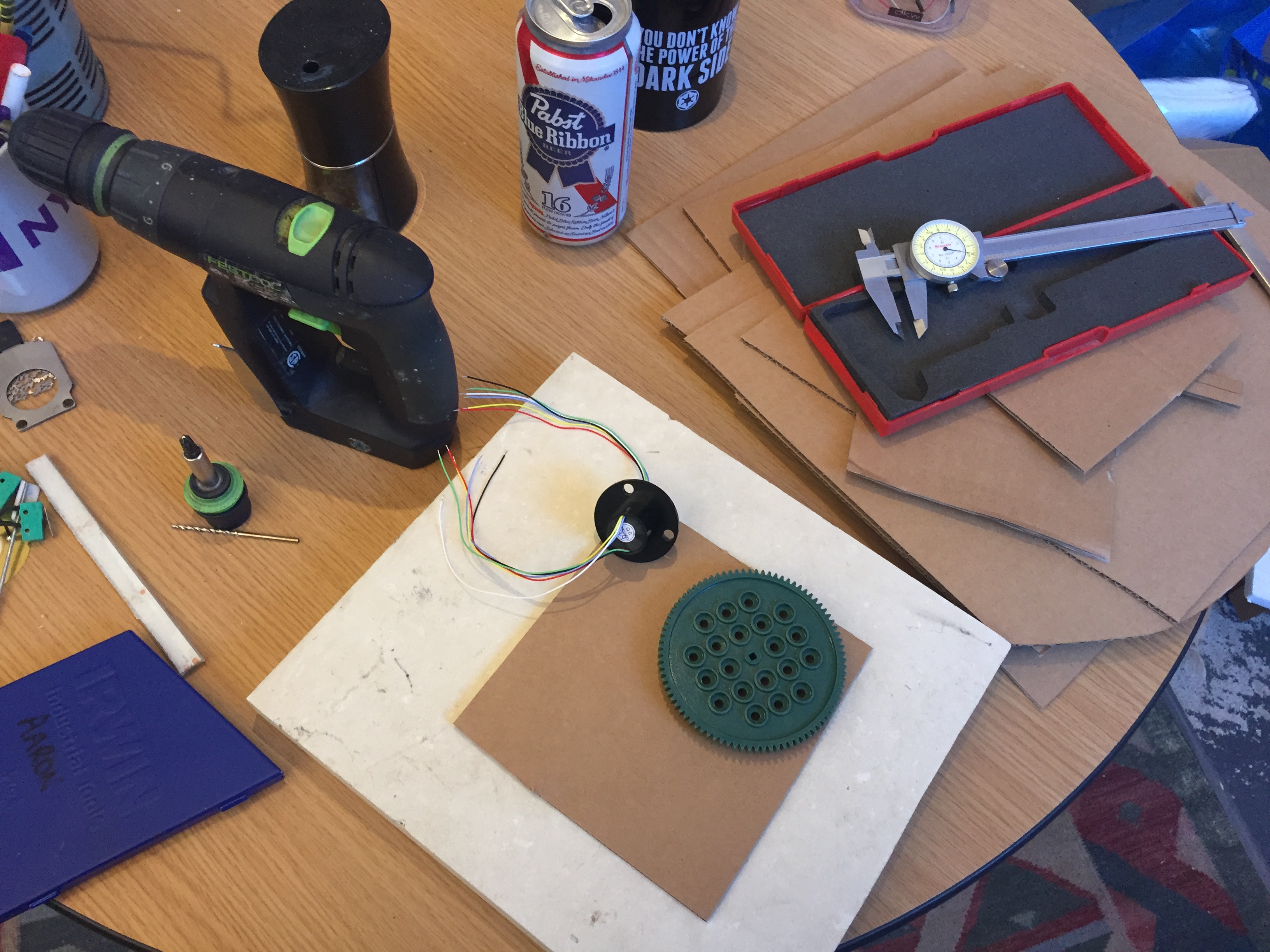
Now that the projector was accepting video it was time to start on the mechanisms! I always try things with cardboard first:
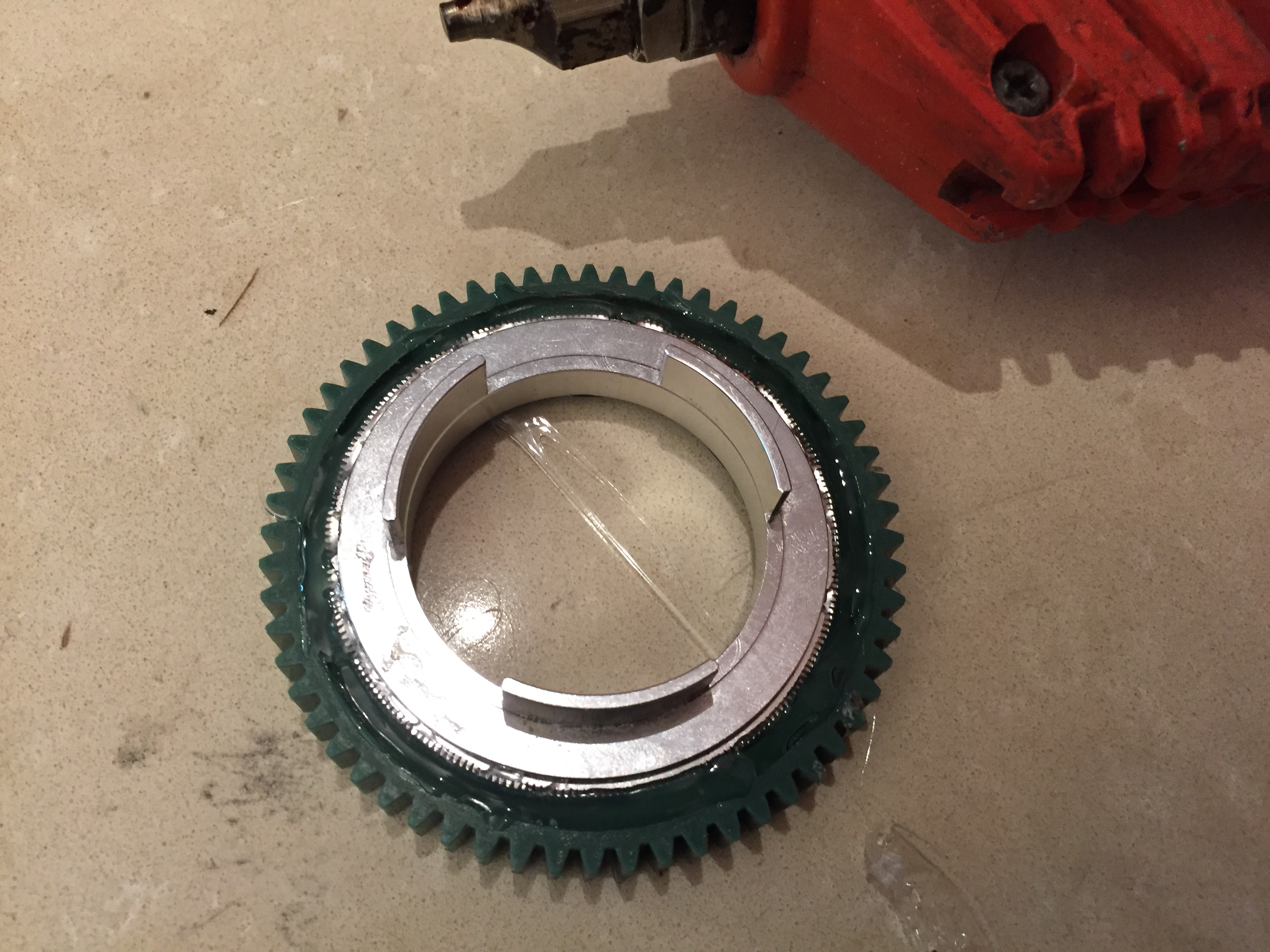
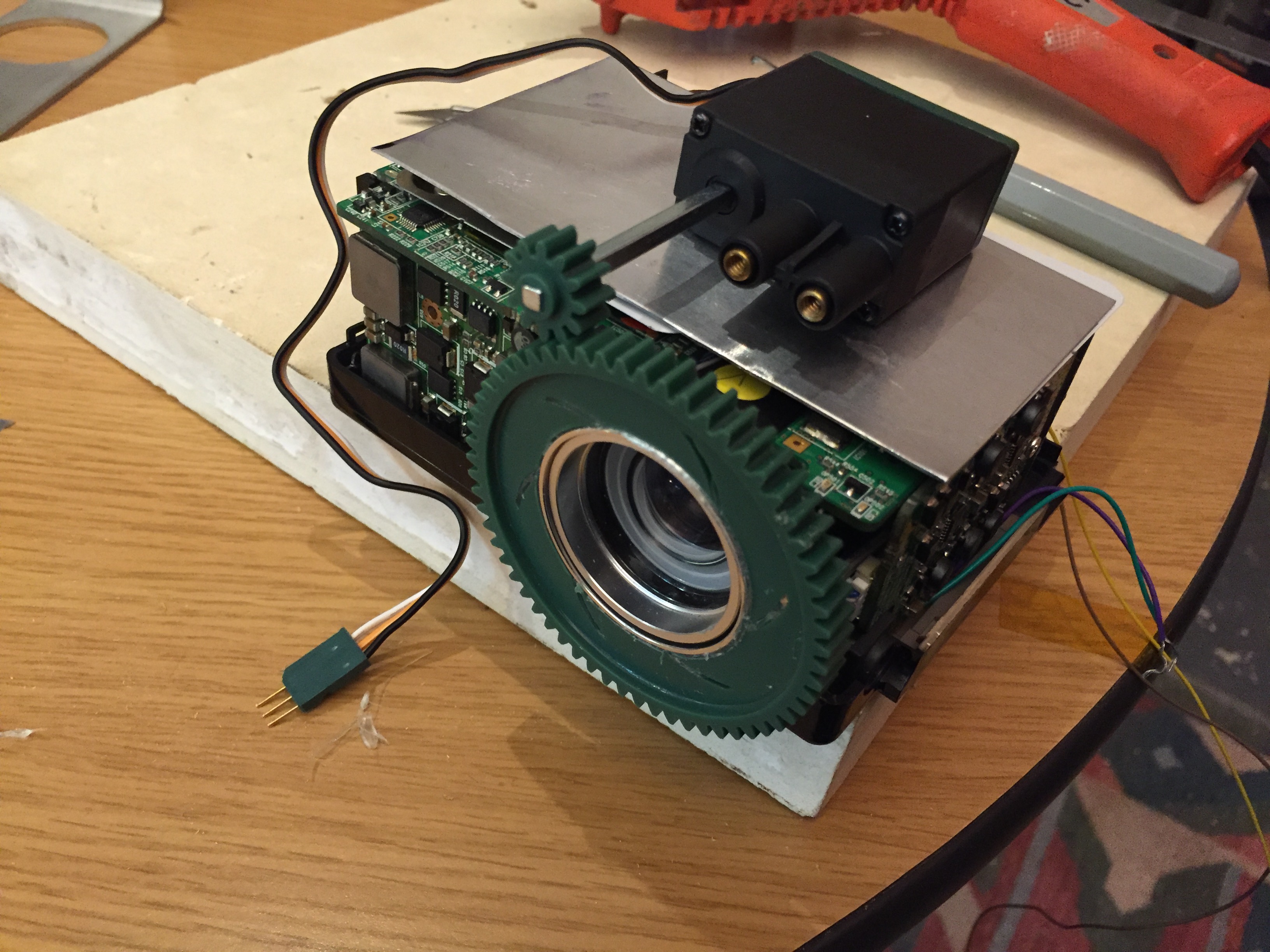
I glued a gear onto the focus ring to control the projectors focus remotely. It took two tries to get it centered:
My first of many mechanical mistakes on this project was un-supported shafts. My second mistake was my gear ratio. I eventually moved up to a 36 tooth gear on the servo instead:
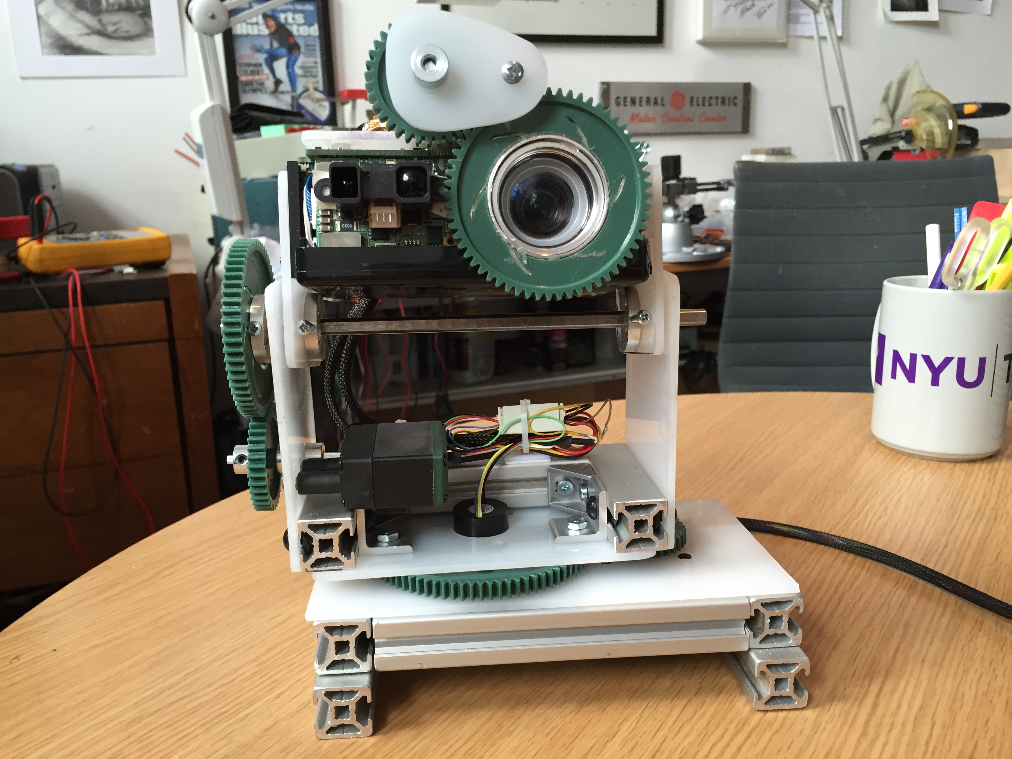
I decided to build all the structure of my new robot friend out of scrap acrylic. The three laser cutters in the shop were pretty booked, so I cut everything on the scroll saw.
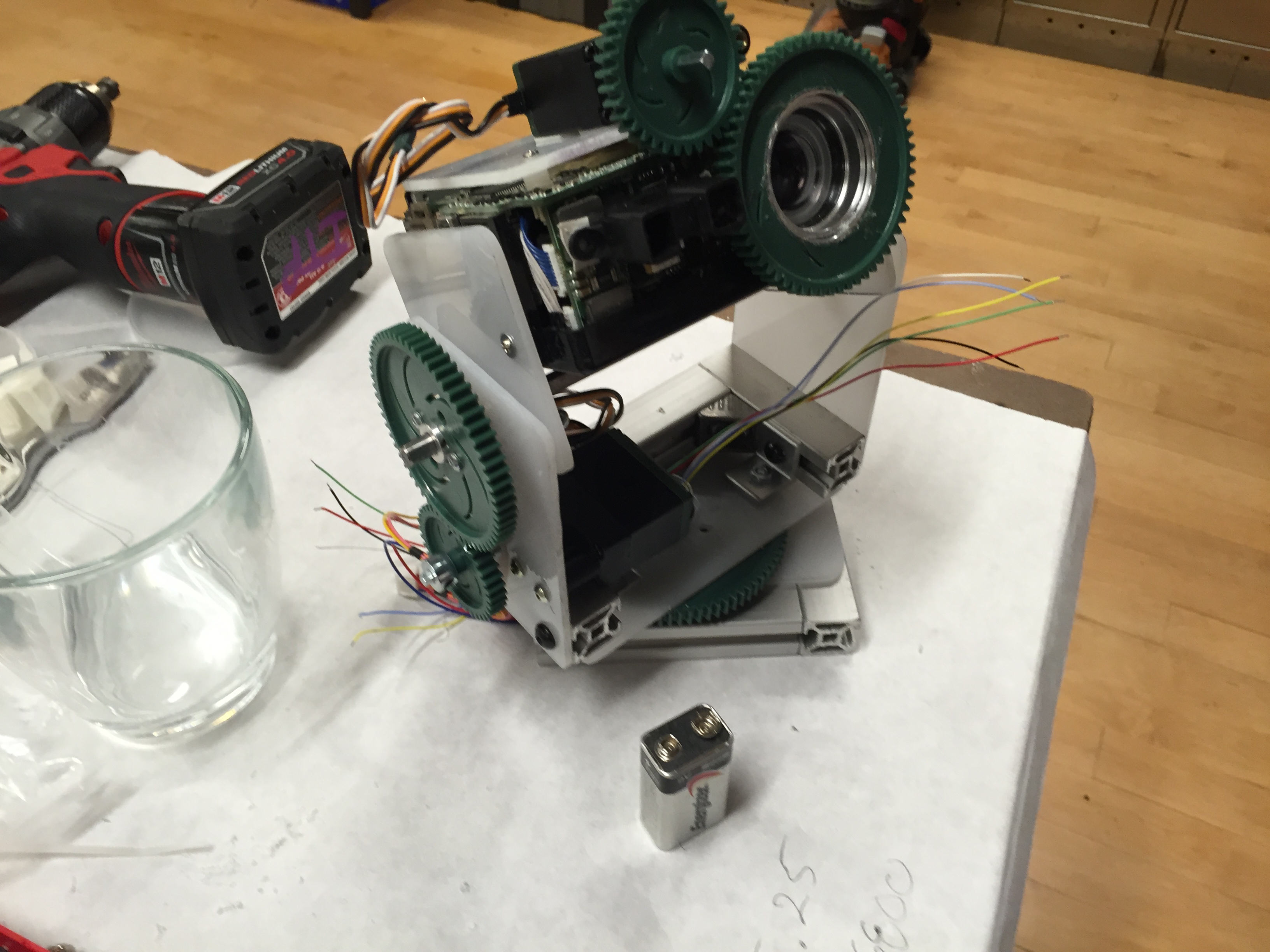
My second big mechanical mistake was undersizing the PAN stepper motor. The light was not budging a millimeter using it. Unfortunately I had to chop open the base the night before to fit a larger stepper motor to move the light.

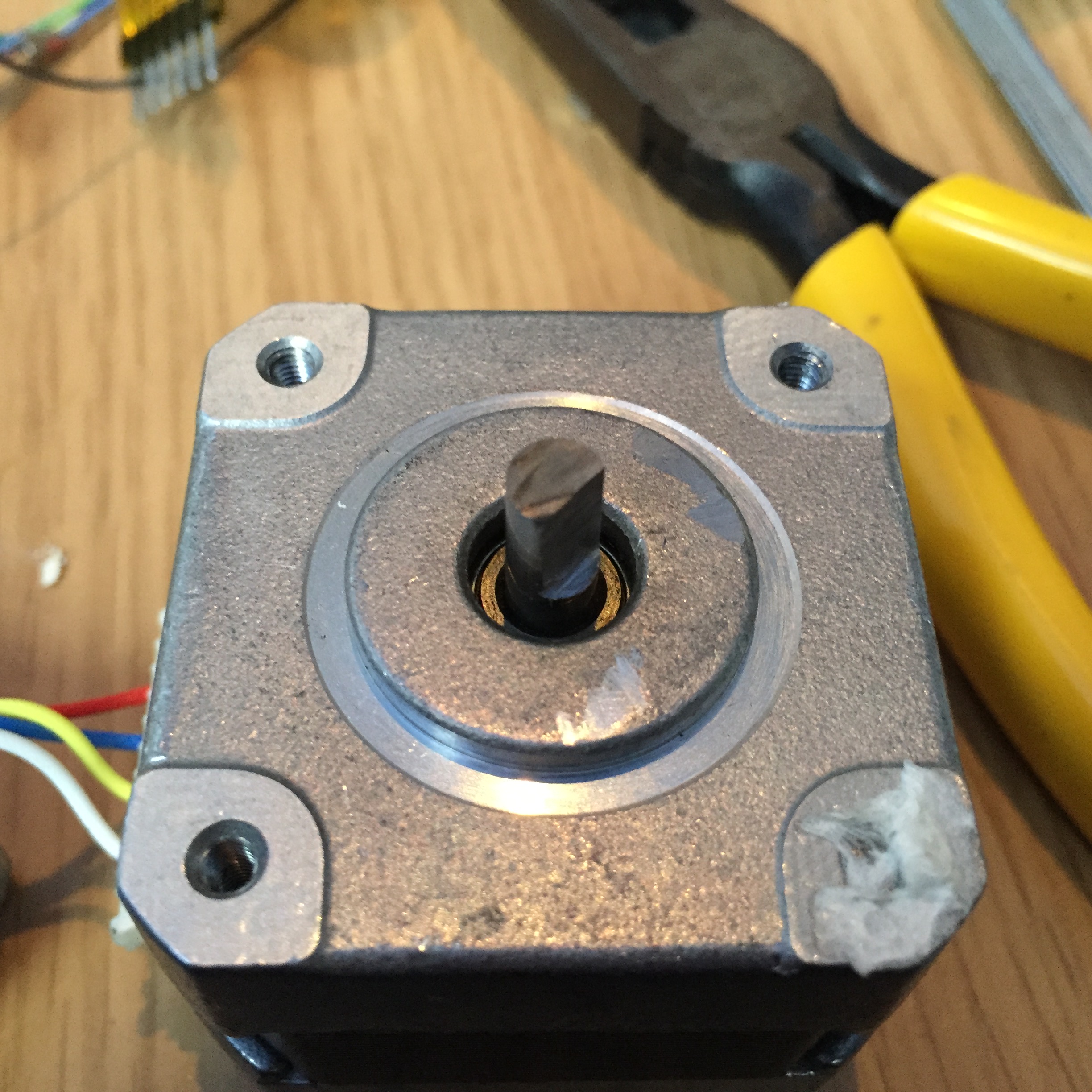
I had to cut the shaft down, and notch it so that it didn’t slip on the 36t plastic gear. I did this with the thin cut-off wheel on a dremel. I was pretty happy with the result!
Later on I redesigned the base to fit the larger stepper motor. This is my first time working with T-slot tubing. This stuff is great!
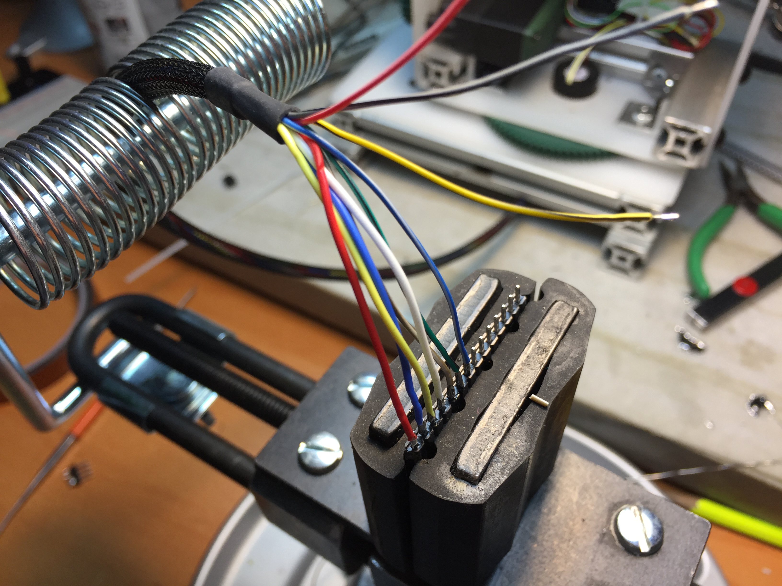
I also went ahead and sleeved all the wiring on the project:
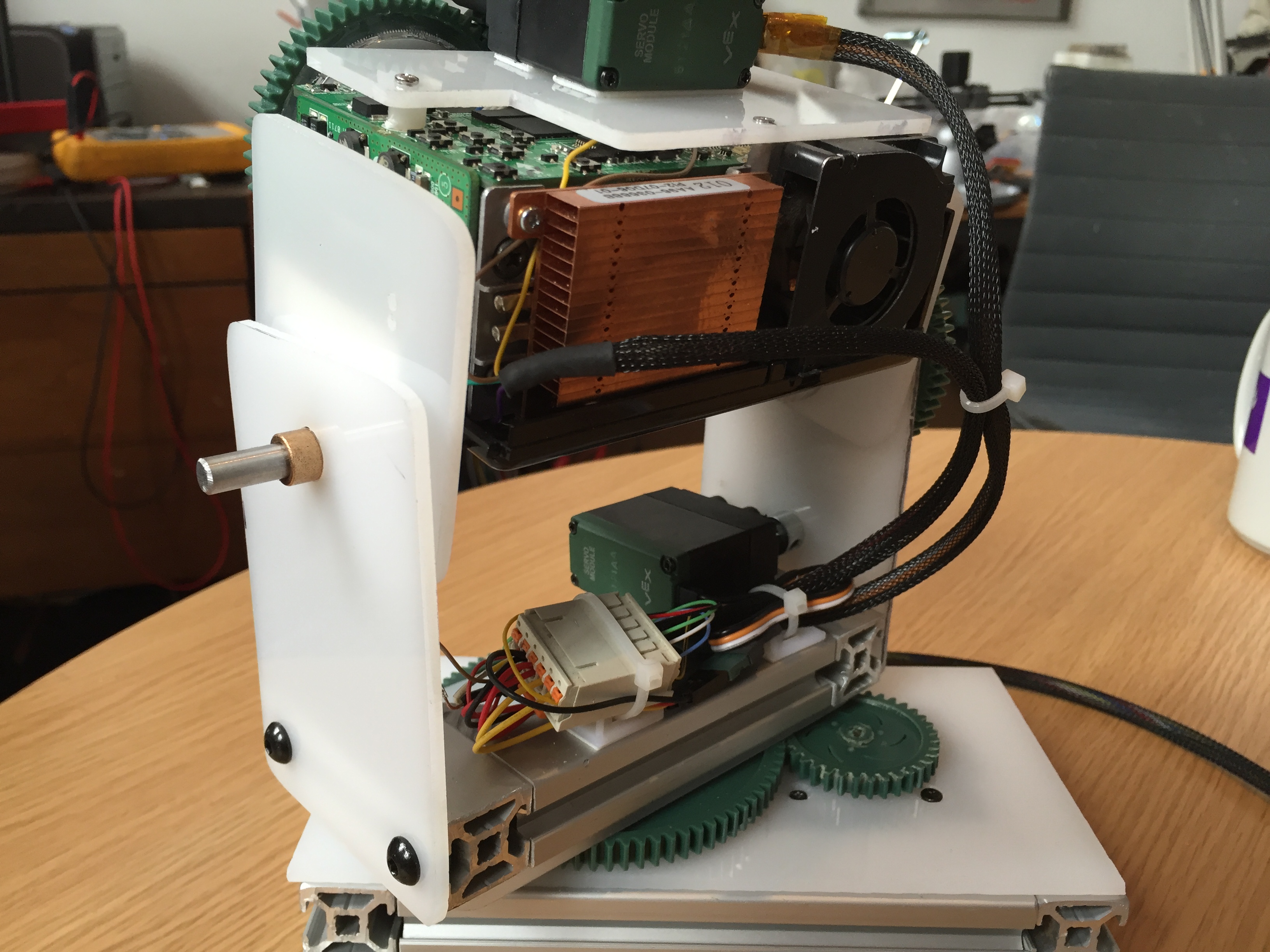
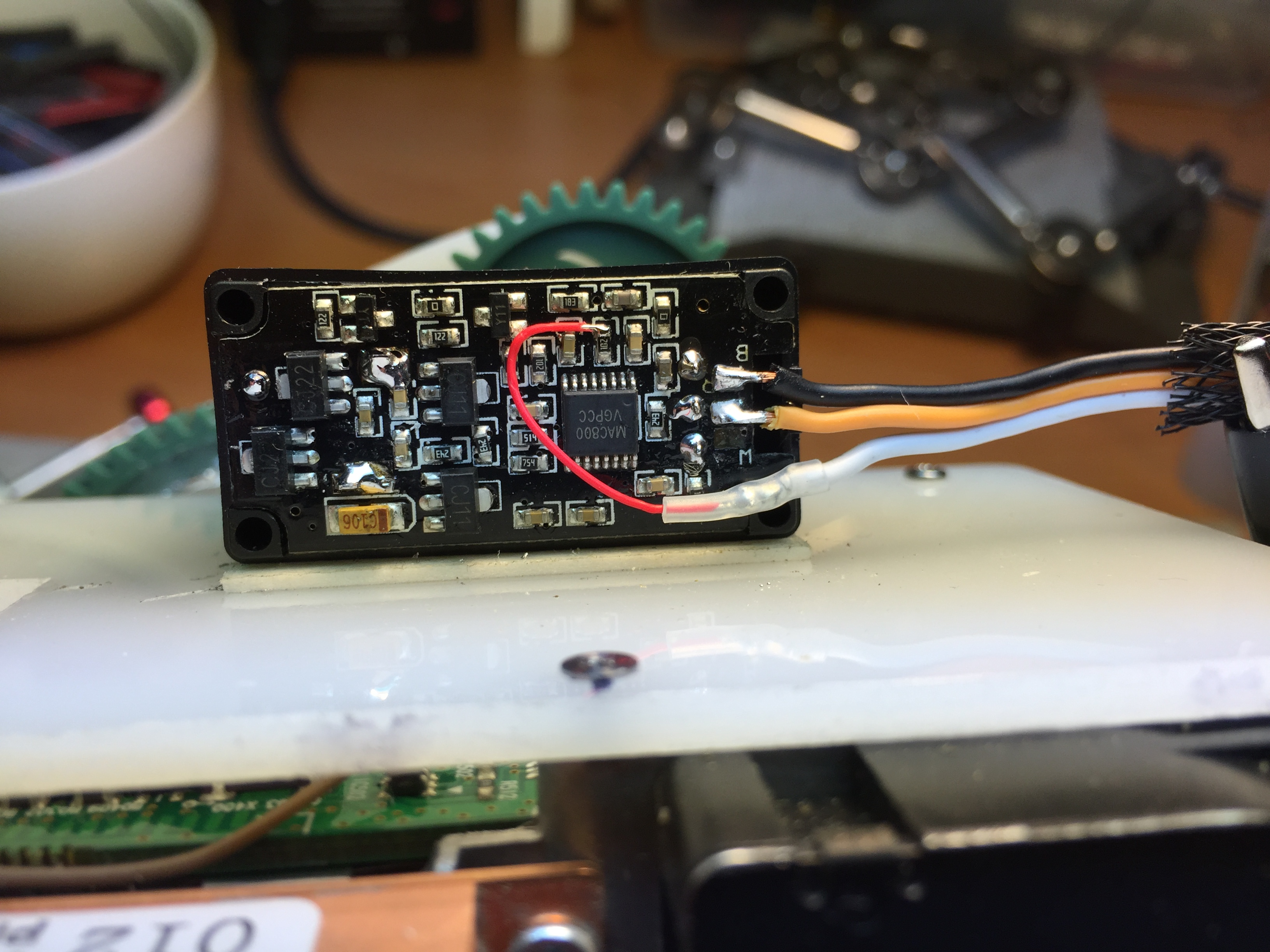
Of course in the process I tore a pad off the PCB of one of my servos! Of course I only bought two. Another repair for my robot friend:
Im very happy with the final product. The full rotation is a great addition.
The main thing I would like to change is the placement of the tilt pivot point. The center of gravity is much higher, and tilting would be much smoother if I moved it.