Final Documentation – Beats Exposed

The Project

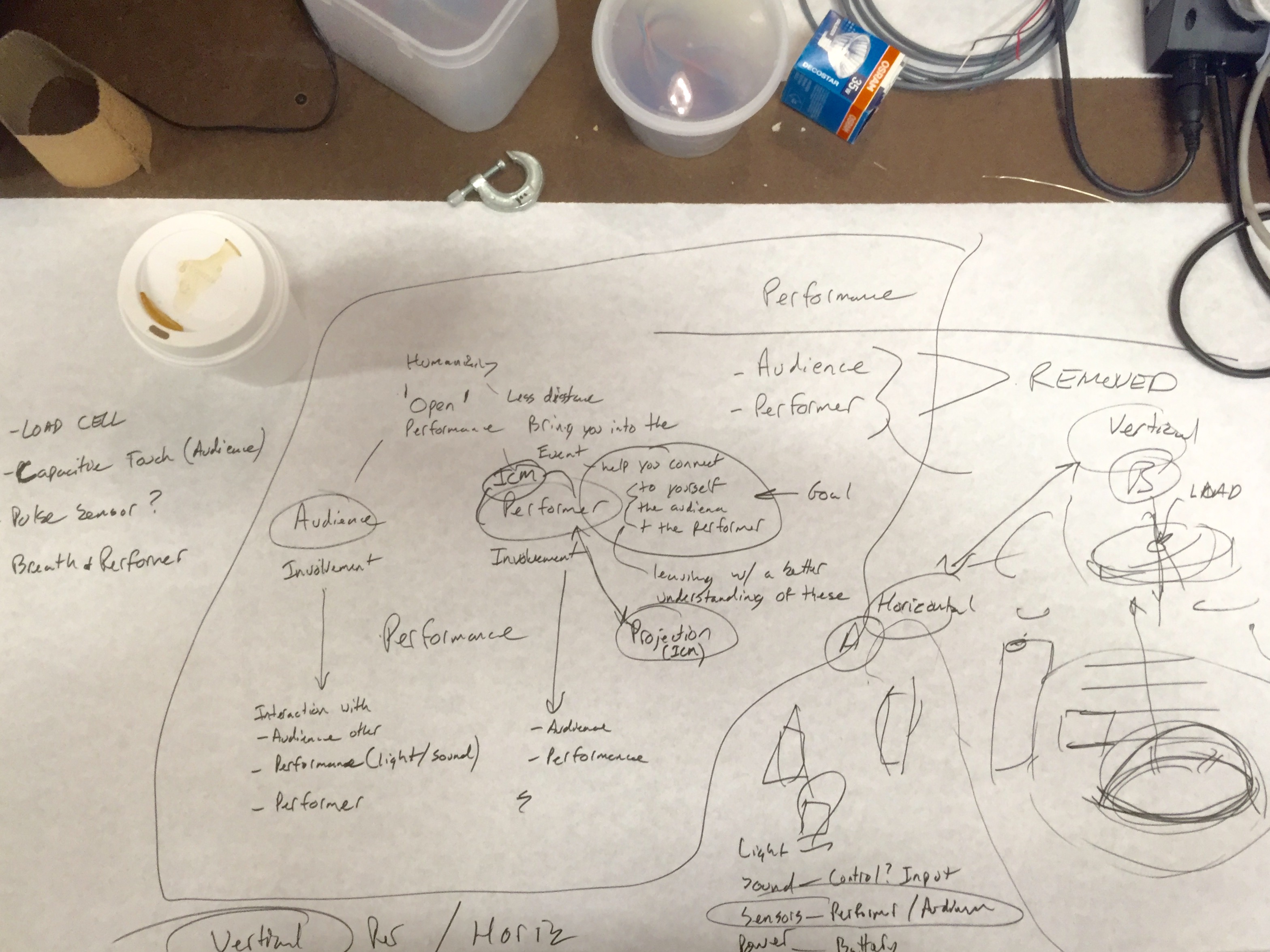
Beats Exposed is an interactive performance experience that breaks down the barrier between audience and performer. By exposing the body’s vital signs, the performer invites the audience to see beyond the polished act and into the extreme physical and personal effort.

Beats Exposed is built to be used in performance on, or off, stage. It is lightweight and able to run in a variety of settings.

Our current iteration of the project is performed with an aerialist. It exposes the exertion in an artform that is extremely demanding, yet typically meant to appear effortless.

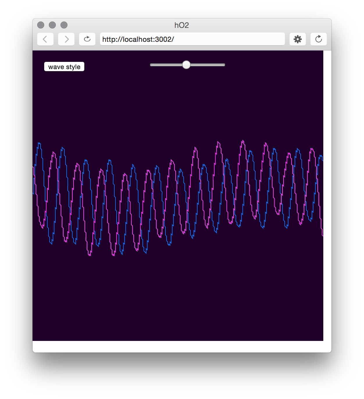
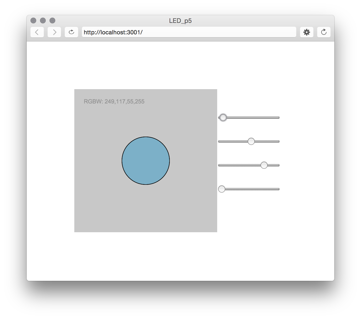
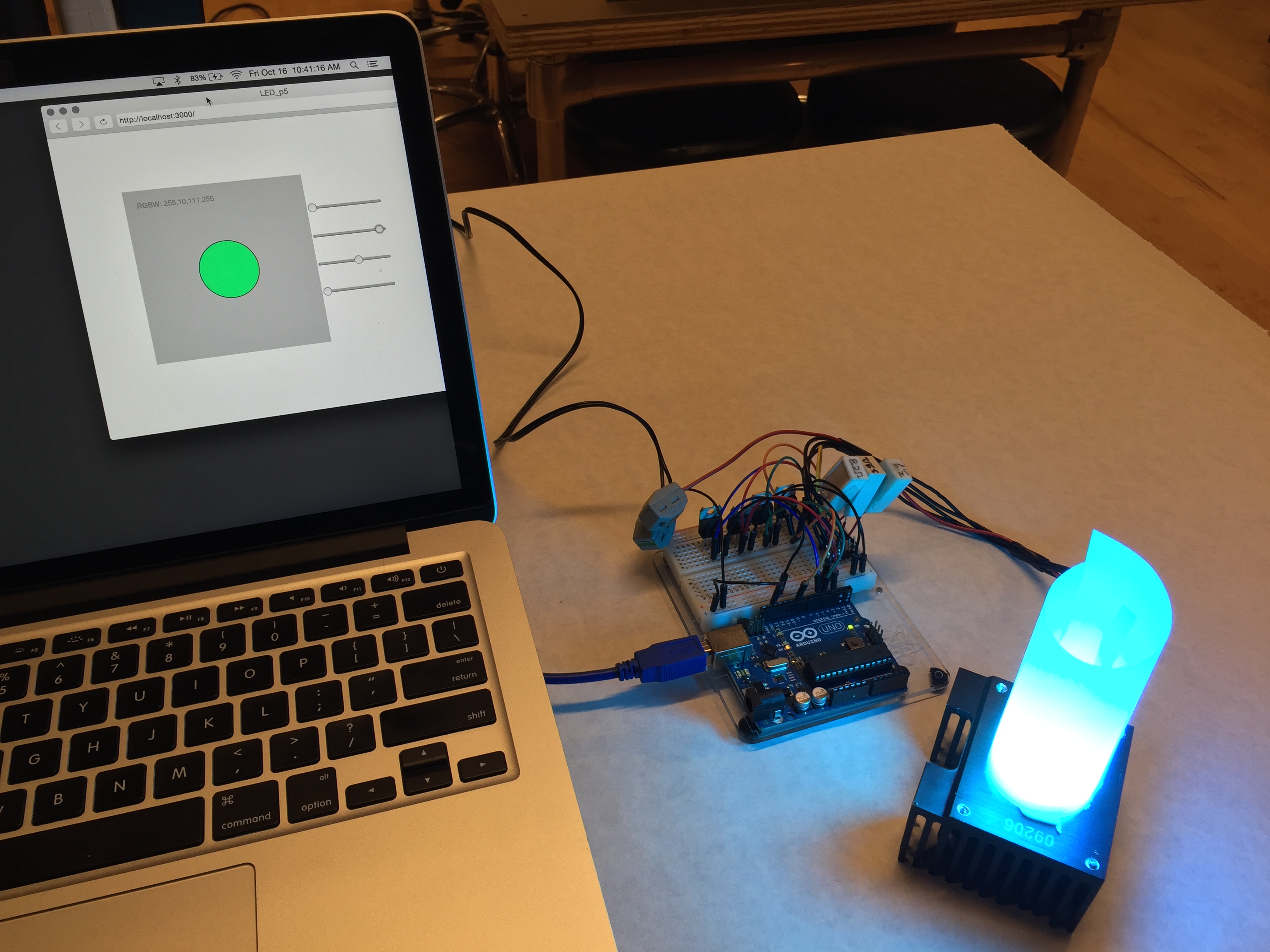
Or project senses the aerial performers heartbeat with a Polar pulse sensor, and sends this pulse wirelessly via two Moteino boards. The pulse is then used in a P5 javascript sketch to effect audio and visualizations.

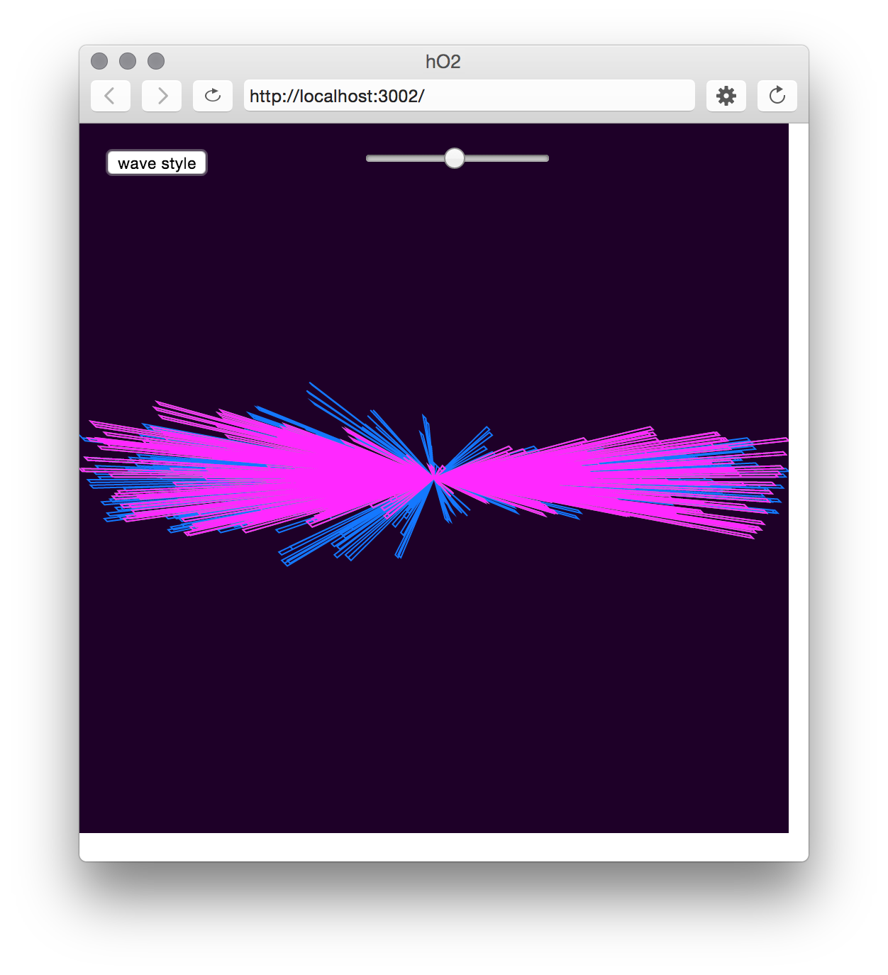
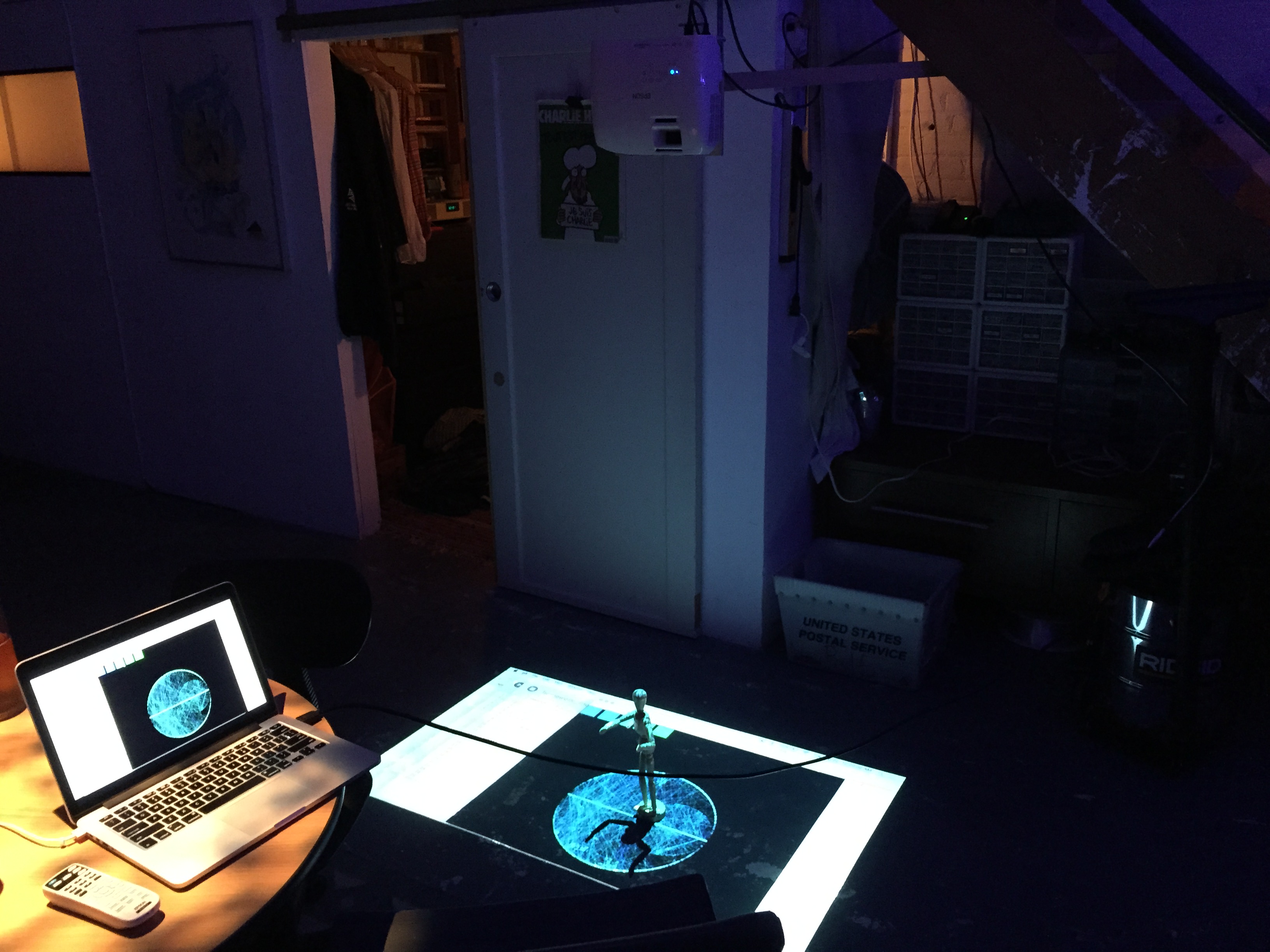
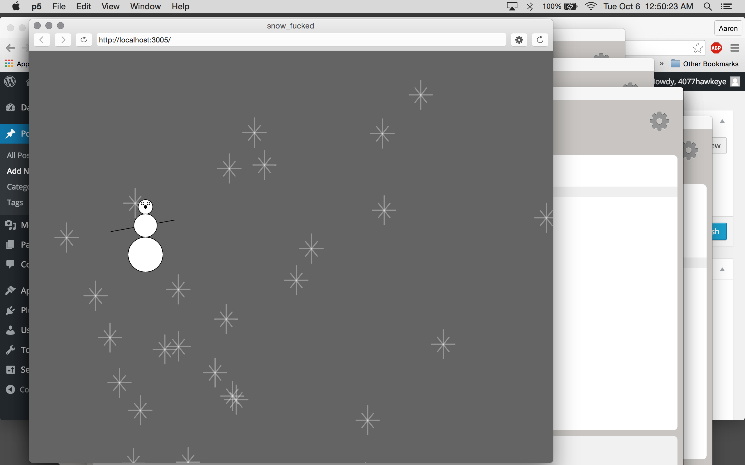
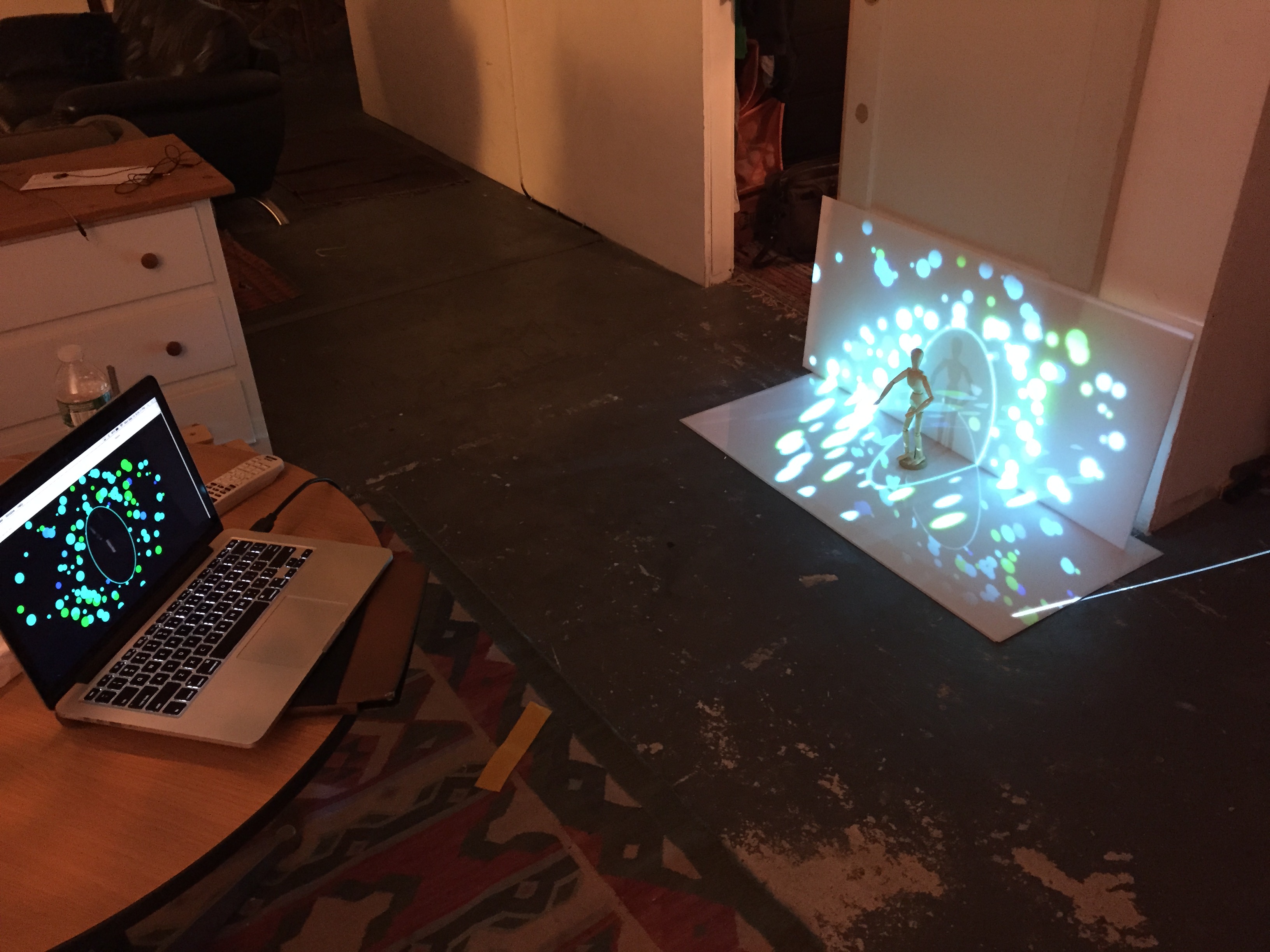
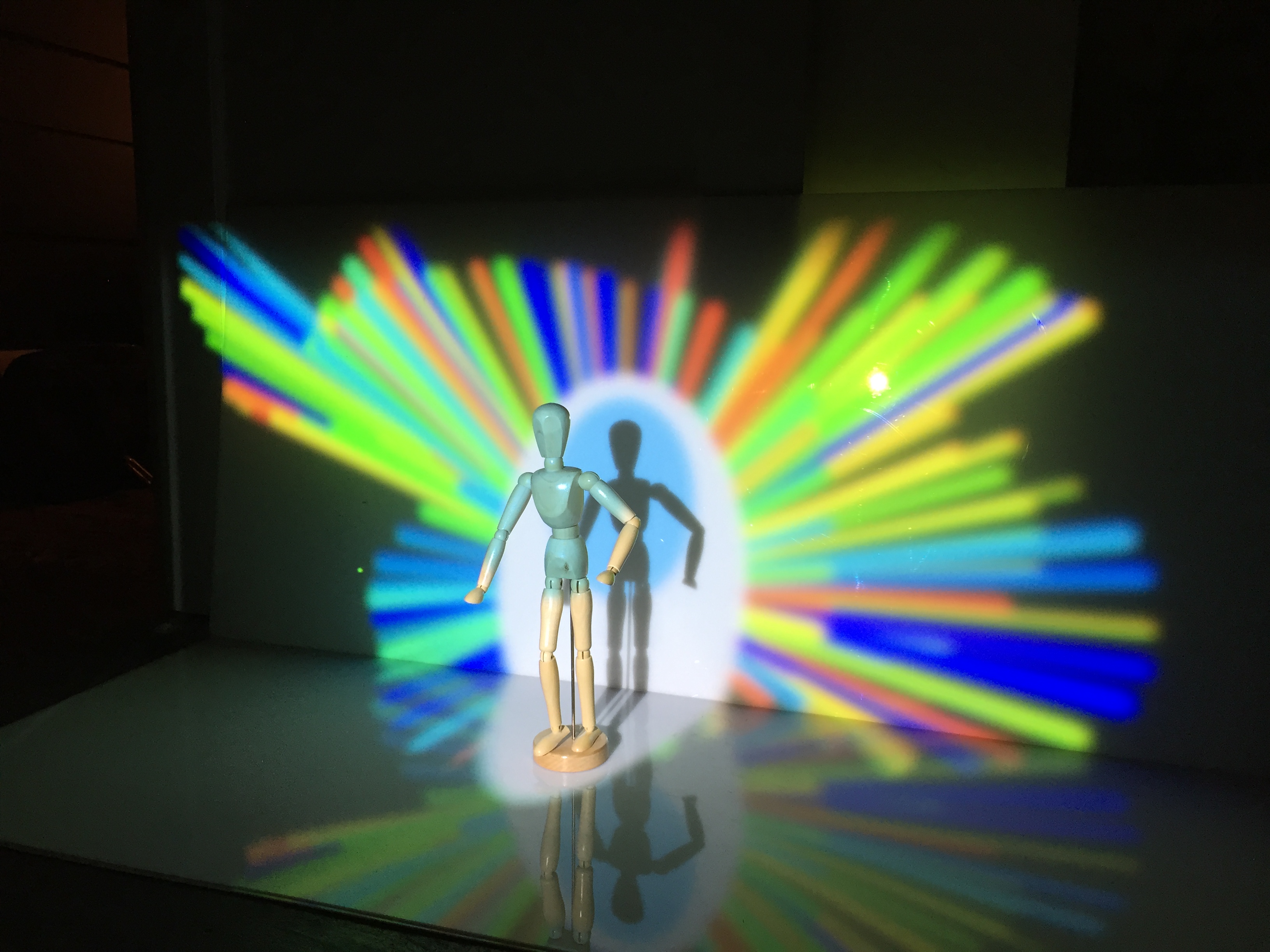
In this experience, the audience hears the sound of a heartbeat timed with the performer’s pulse. The visualization, also reacting to the pulse, projects from the ceiling onto the performer, surrounding area, and any audience members that have come in close. The resulting experience is intimate, personal and engaging.

_A1A0183
_A1A0206
_A1A0236
The polar band is able to send a reliable heart pulse even during movement

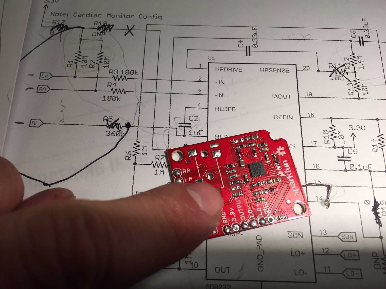
Our method for measuring the heart beat of the performer changed drastically over the course of our testing. The first version we used worked via sticky electrodes attached to the chest and connected to an EKG operational amplifier which amplifies the minute voltages generated by the heart. We quickly ran into noise issues when the performer made any slight movement. After trying some simple signal processing in arduino, as well as modifying our EKG breakout board to include heavy filtering, we found it very hard to get a reliable signal.

After a lot of research into portable EKG units worn by the ‘patient’, I began to learn the importance of using an accelerometer alongside the electrodes in order to filter out movement noise. The first time I heard of such a thing was buried in a youtube video:


Screen Shot 2015-12-15 at 11.53.24 AM

Combining the operational amplifier with an accelerometer via a small microcontroller is also in the datasheet for the heartrate sensor.

Trying to implement this kind of digital signal processing ourselves was quickly starting to look too difficult for a project due in 2 weeks!

Trying to change around the circuit on the breakout board was a challenge!

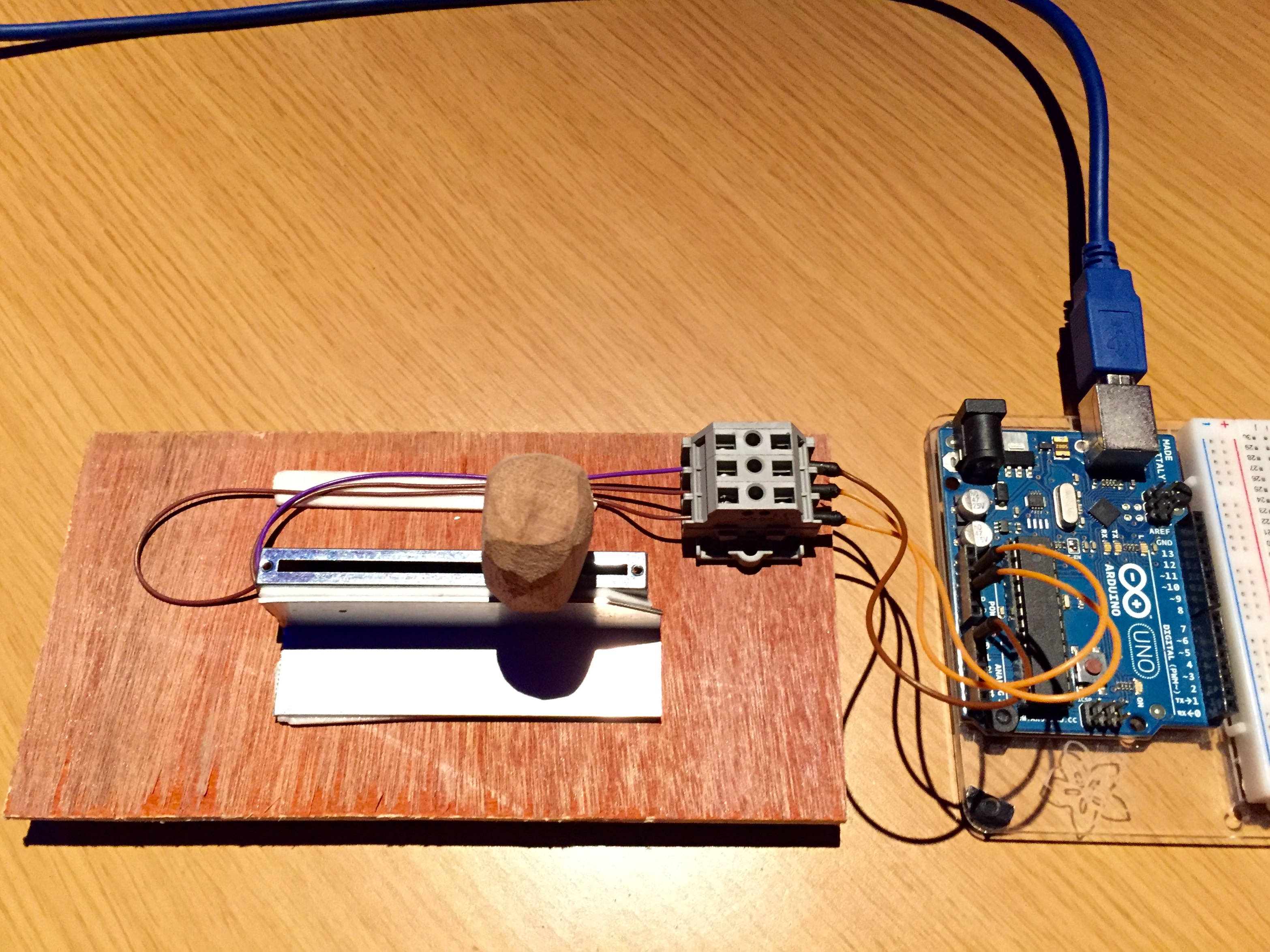
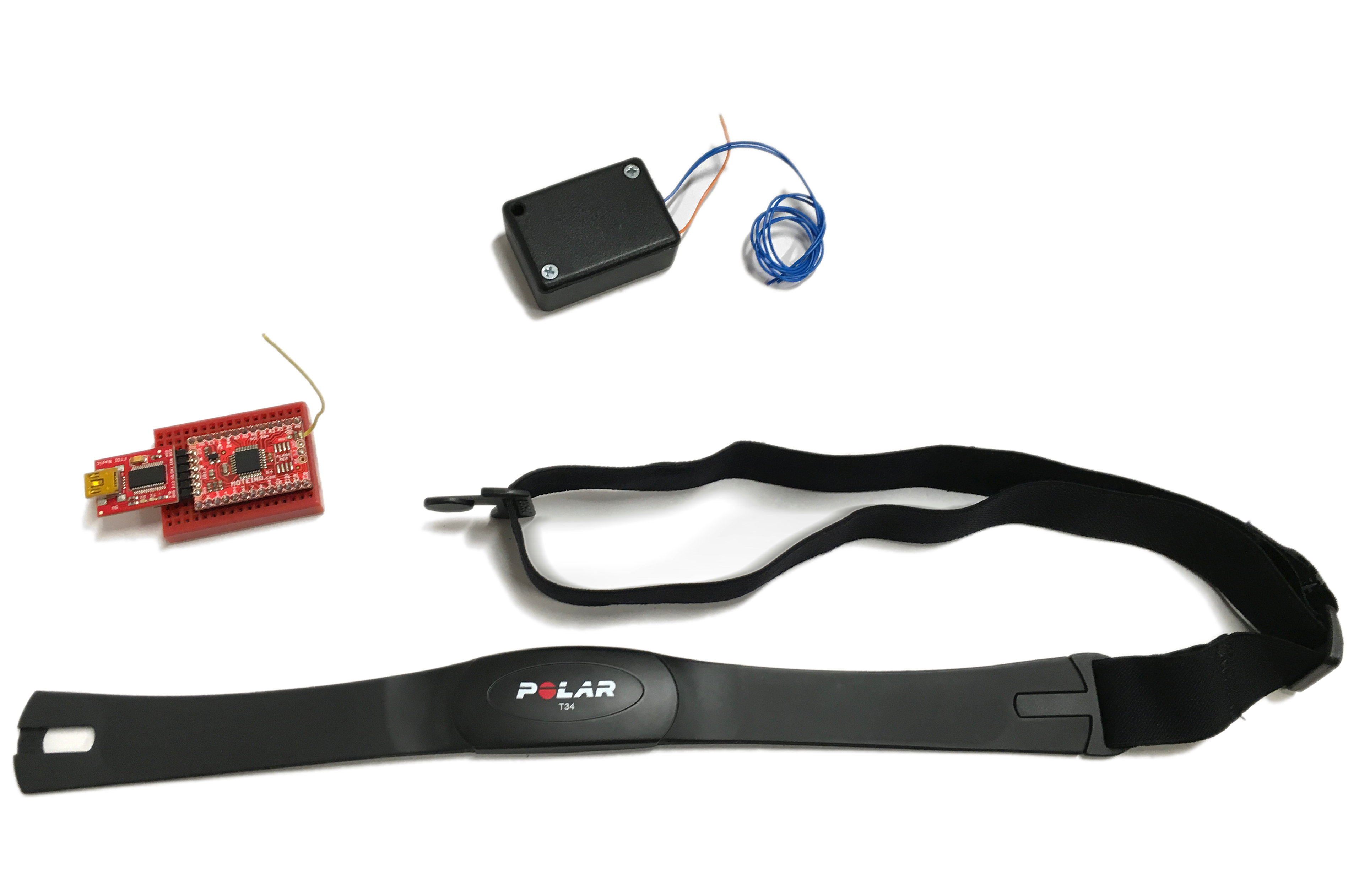
Eventually we found a product–the Polar T34 pulse monitor that handles this processing. By using this band as our sensor, we were able to get a very accurate heartbeat pulse that was free from noise even during movment.

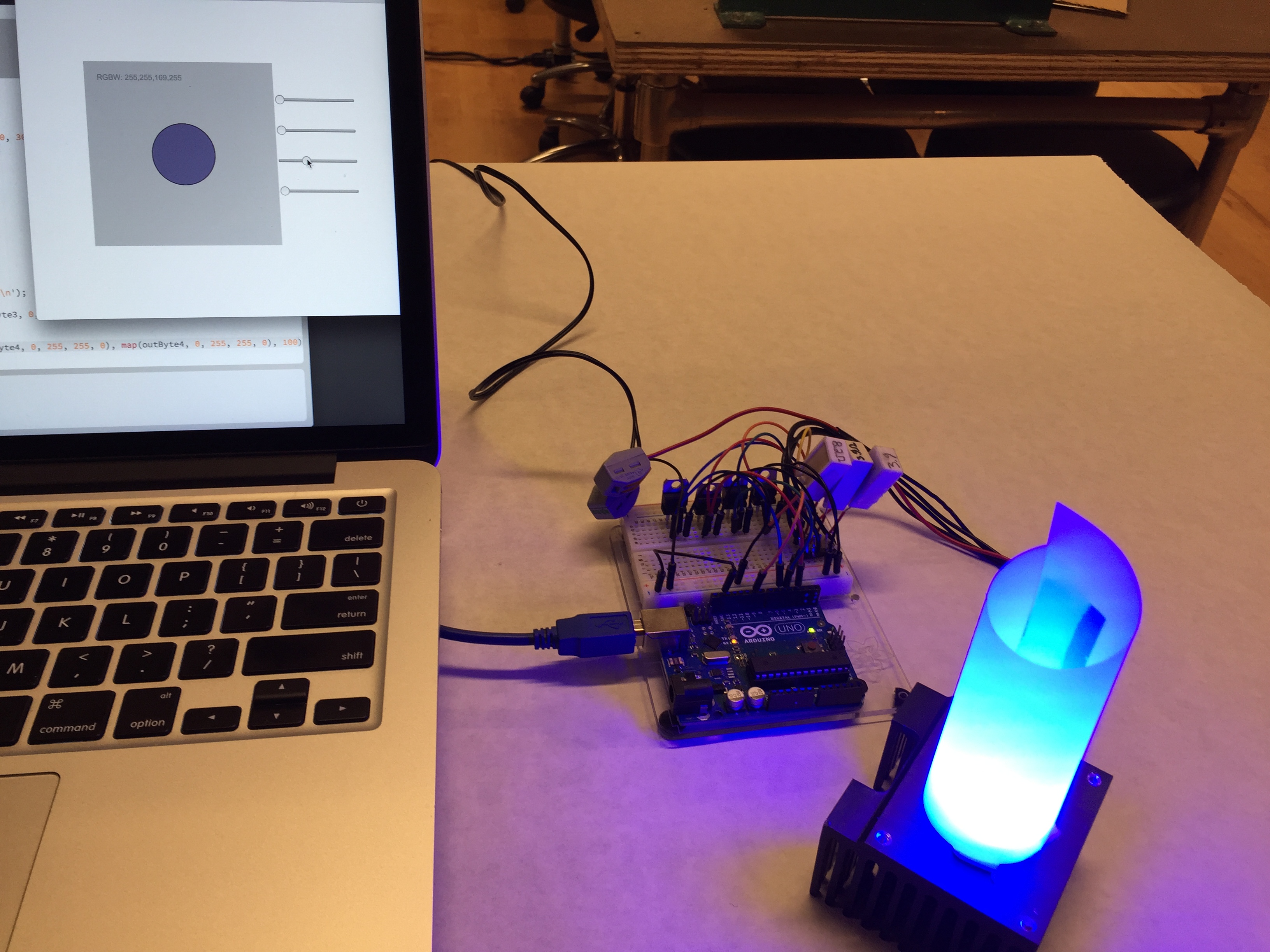
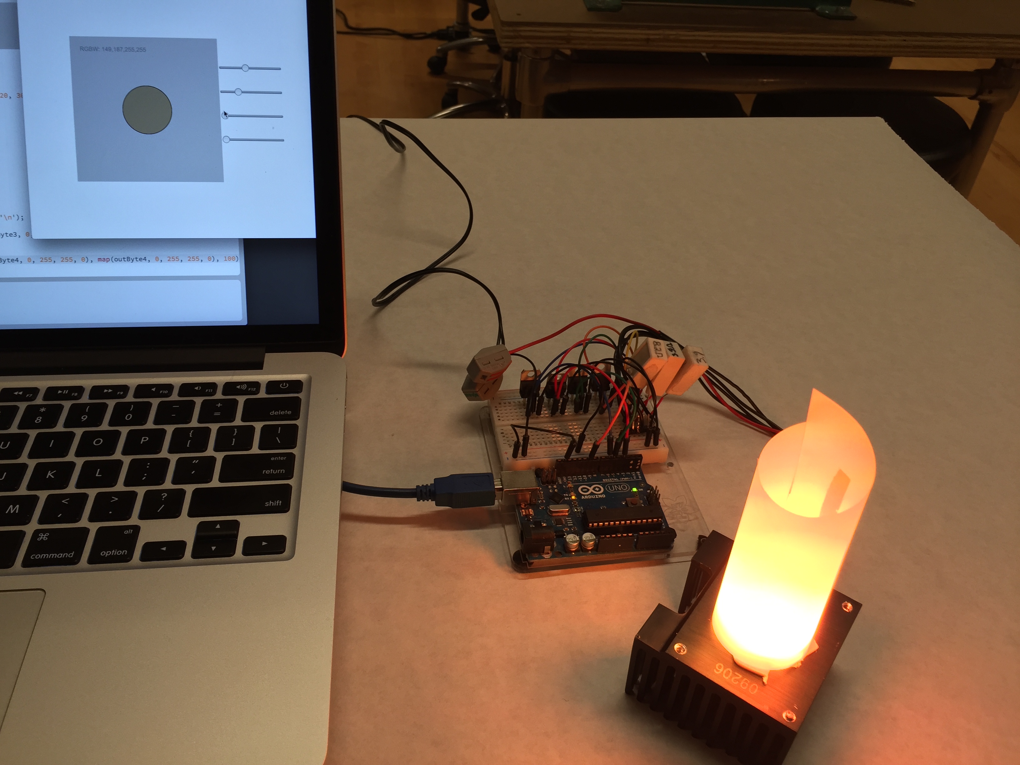
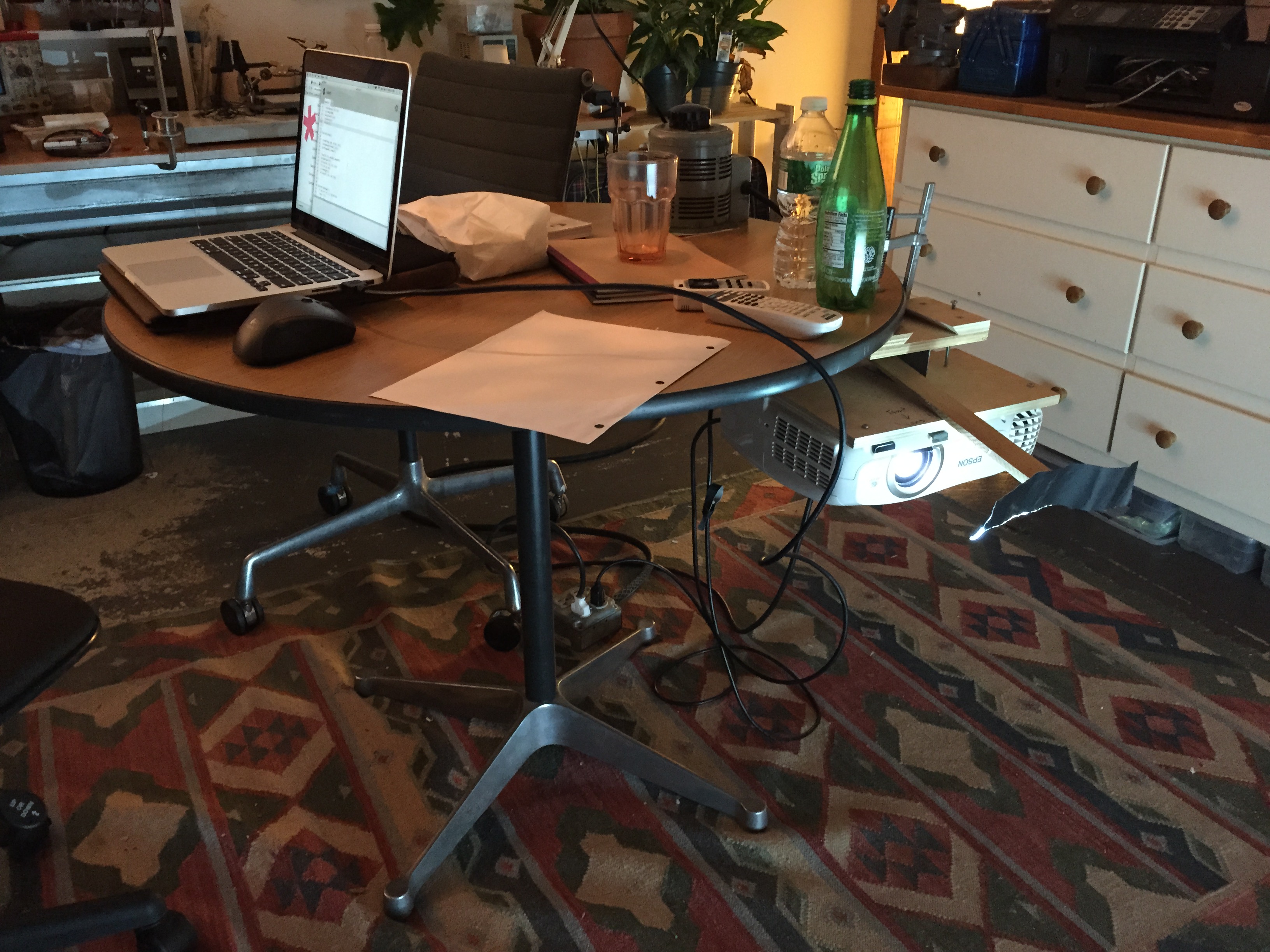
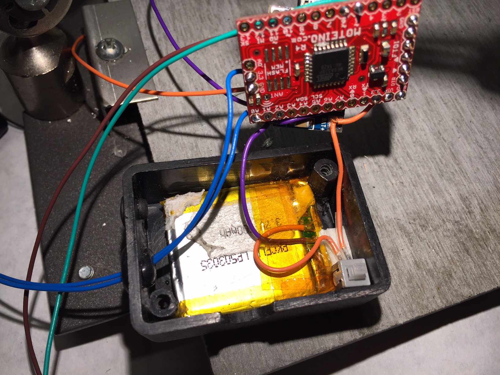
Our final human interface works by receiving a pulse signal from the Polar monitor for every heartbeat, which is then transmitted wirelessly via a Monteino transmitter (over a 915MHz serial bridge) that is worn by the performer. This 915MHz signal is then received by a second Moteino that sends the pulse along to P5 via serial. In order to make sure that P5 sees every pulse, each heart beat is about 320ms long.

Our project used lots of Kapton tape to insulate between the battery and three circuit boards

Our original proposal included a breath/stretch sensor in addition to the pulse sensor. We thought implementing this would be relatively simple. In reality, the stretch sensor was very sensitive to movement and we were unsuccessful at getting a usable reading.

It took three iterations over about one month to get the pulse sensor working as we intended. We tried an optical pulse sensor, a three electrode EKG heart monitor, and a two electrode heartbeat monitor. All three of these sensors were plagued with electrical noise whenever the performer moved. Finally we arrived at the Polar T34 heartbeat band, which is designed to produce a reliable heartbeat even during times of heavy physical movements. We found this band provided an extremely accurate representation of the performers heartbeat, even when they were moving.

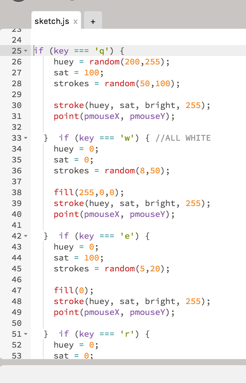
We spent a lot of time working with the the serial communication to get a reliable signal. Once the signal was in P5, we found we had to simplify our sketches significantly in order for them to run reliably. In the future we would likely try to use Processing for visuals.

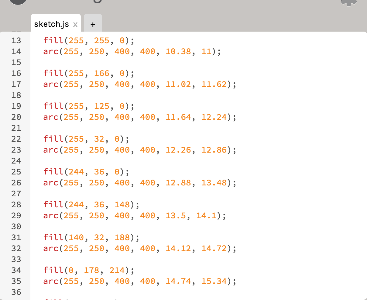
Our final code for the project can be found on github: https://gist.github.com/lisajamhoury/e8a7de48f8155078efe2

Interestingly, some of our testers had a negative reaction to the sound of the heartbeat played over headphones. We don’t yet understand why some find the sound unbearable, while others find it centering and calming. We will continue to refine the sound and user test to get a better understanding of this sensitivity.


ICM Final – Humanizing Performance art

The key ingredient in performance art of any kind is the human performer. For our ICM final, Lisa Jamhoury and myself would like to use computational media to better translate the action and emotion of a performer to his or her audience. This goal is part of a bigger project that Lisa, Danielle Butler and myself have dreamed up whose focus is for an aerial performance. We would like to draw an audience closer to an aerial performer, and to do so outside the confides of a traditional performance space.

FullSizeRender 4

Every idea starts with chicken scratches (and coffee)

The part of this project we will be executing in ICM will be projected visuals that are manipulated by sensors placed on the performer and the arial apparatus, and possibly ones on/directed to the audience.

My goal is to only use physical inputs that will produce definite translations. I think using inputs that we can fully count on and coding them work as fluid as possible is key. (I’m not sold on the xbox kinect).

Some of what I’ve been doing in p5 earlier this semester will prove to be very helpful as basic stepping stones in this project.

Manipulating p5 elements via serial data and physical sensors:

visuals based on sound:

Screen Shot 2015-10-27 at 8.46.34 AM


A lot of visuals that our classmates have done come to mind:

Jamie Charry:

http://itp.jcharry.com/category/visual_language/

Screen-Shot-2015-10-12-at-11.00.51-PM

Yao:

http://www.wangxinyao-design.com/?p=110

屏幕快照-2015-09-22-2.49.59-AM

My humble moon that Yao helped me with:

IMG_0945


The basis of my idea of interacting with the performer comes from my work restoring a sculpture designed by Robert Rauschenberg. In 2012, I was asked by Trisha Brown Dance Company to restore the electronic set pieces for Astural Converted. The set was composed of eight wireless, aluminum framed towers. Each contains light sensor activated sound and lighting. Designed by Robert Rauschenberg in 1989 and constructed by engineers from Bell Laboratories, the towers turn off and on their lamps based on the performers movements. Each tower also plays a different part of the musical score via individual tape decks. .

Screen Shot 2015-10-28 at 10.54.34 AM

Screen Shot 2015-10-28 at 10.54.42 AM

Im excited about taking this idea of car headlights  and tape decks controlled by a dancers movement, and scaling it up to p5 and digital sensors.

Hipster Oscilloscope

This week I used the p5 sound library to map an oscilloscope to the microphone on my computer. This came after a week of frustration trying to work with RGB pixel tape and p5. I definitely need some more time to get that working! I decided learning about routing sound in p5 would be a good fall back.

The code used the waveform generator in the p5 sound library to draw three waveforms:

By toggling a DOM button, you can switch between two visualizations.

Screen Shot 2015-10-27 at 8.46.25 AM

Screen Shot 2015-10-27 at 8.46.34 AM

The slider controls the volume / amplitude.

Here is the sketch:

http://www.aaronparsekian.com/projects/oscilloscope/

p5 serial RGBW candle

This week we worked with DOM libraries in p5. I decided to use four DOM sliders to control a 40Watt RGBW LED by outputting serial from p5 into an arduino.

The code to do this took a lot of trial and error on the serial side. The outputs from the four sliders are made into a serial string, then parsed in the arduino code to four analog outputs.

Here is the p5 code:

and the Arduino code:

The sketch is very simple looking 🙂

Screen Shot 2015-10-16 at 11.05.21 AM

I mounted the RGBW LED to an old pentium II heatsink, and connected the four anodes to the arduino’s analog outputs through four TIP120 transistors.

IMG_1106

IMG_1105

IMG_1103


Synthesis Friday – Pong

Last Friday we worked in groups learning how to interface the Arduino with p5 via serial communication. My partner Yiting and I decided to make a pong inspired game that was controlled via a linear potentiometer.

FullSizeRender 3

Our code turned out fairly simple. At some point I would like re-write it into objects. Also a two player version would be fun!

Here it is in action!

Assignment #5

This week we worked with objects and arrays. I made a simple program using a snowflake object that Nilomee created. I put this snowflake in an array. My hope was to make the array repeat once it reached its highest value. But after messing with it for hours I couldn’t. I also made a shameful snowman object. At least his arms wave. :/

Screen Shot 2015-10-06 at 12.50.23 AM

http://www.aaronparsekian.com/projects/ICMassignment5a/

Assignment #4

This week we learned to use functions. I built the same program as last week, but eliminated almost 100 lines of code!

Most of this was done by putting the ten buttons mouse pressed properties into a for loop, and putting the buttons size and color in a function, then calling those colors to the lines being drawn in the circle.

Here is the program:

http://www.aaronparsekian.com/projects/ICMassignment4

And the code:

Assignment #3

This assignment was done as a collaboration with Xinyao Wang and myself.

Yao and I created a program that draws lines between random points within a big circle and a little circle. There are buttons at the top that toggle what color line is being drawn. Learning about the logic to create buttons that click and stay on was a huge step for me. Also watching Yao figure out the geometric equations at lighting speed was another huge step for me!

I was also really excited to learn that frameRate() works either way. For some reason I assumed that it could only be used to slow the default 60fps down. In our program on my new macbook pro, we have it running at 1800fps instead. Drawing these simple lines is no problem for a modern computer, even at 1800fps.

We used Adobe’s color wheel site to choose colors. It also happens to be an excellent example of interaction on the web:

https://color.adobe.com/create/color-wheel


screen2


screen1

And here is the code:

http://www.aaronparsekian.com/projects/ICMassignment3/

Programming this did not come without its frustrations! Mainly we tried everything to get rid of the horizontal line. It seems like the program enjoys writing horizontal lines very often.

I decided to keep up my projection theme. This time from a new angle:

IMG_0945

Here are some quick videos of it in action!


Assignment #2

This week we learned about how to control sketches with mouse and key inputs. I decided to write a sketch that could be used with a projector for a live performance.

It includes five different looks that are controlled via the q,w,e,r,t keys. The mouse is used for movement, and left mouse click clears the drawing.

The code is pretty simple. The main part of it runs off an ‘if’ statement linked to the five key presses. Each one uses variables to control color, size, and wether it is drawing a line or a point

screen1

Here is the projection setup 🙂


IMG_0779


IMG_0786


IMG_0787


The program itself: http://www.aaronparsekian.com/projects/ICMassignment2/

And a short video of it in action: