My current iteration of this project lives in three plastic containers from the container store. The project is about 4″ x 6″ and stands 4″ high.
The LED source with some muslin fabric draped over itThe Magnesium and Carbon electrodes in salt water
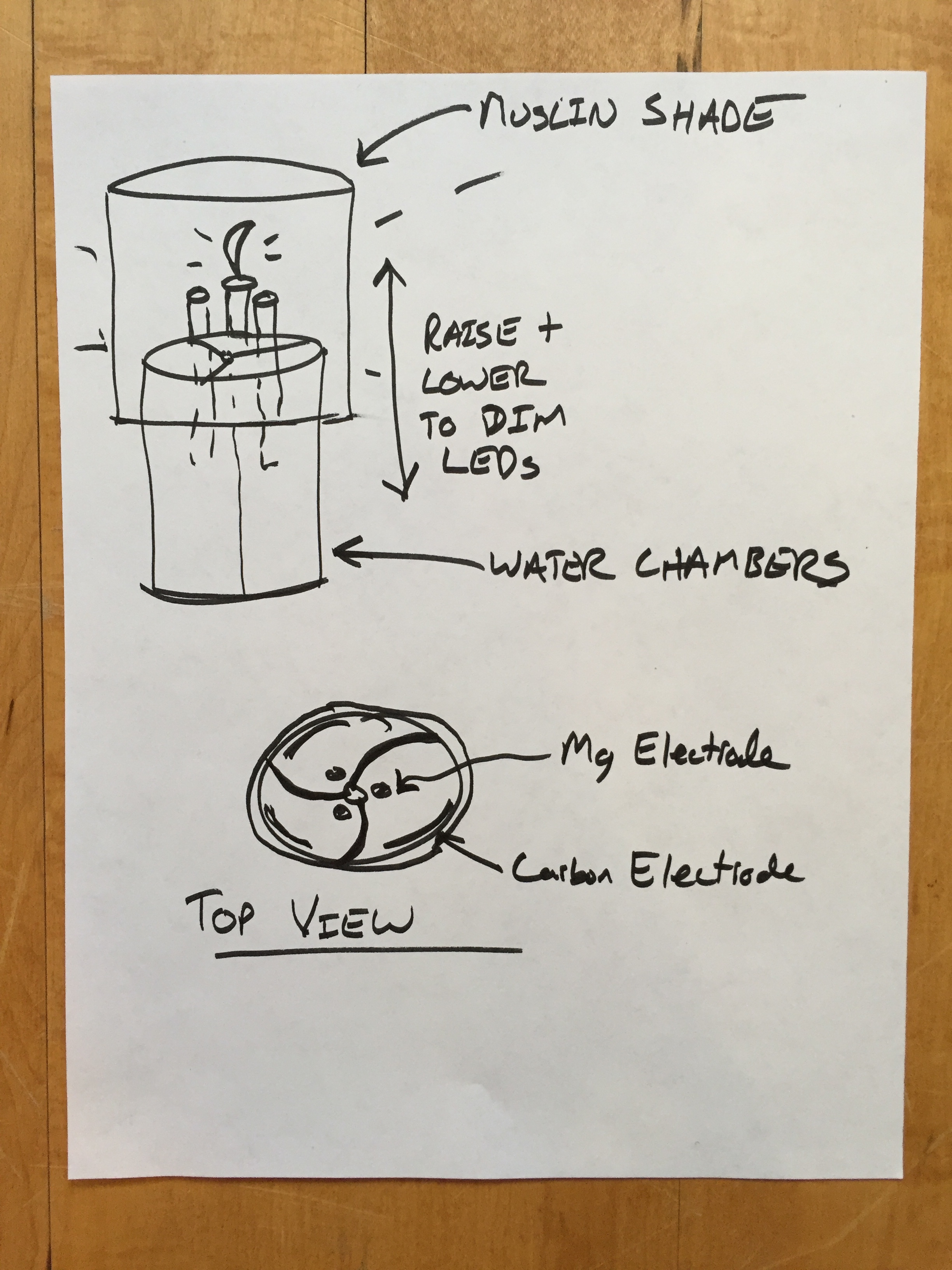
My next task is to work on the form and function. A few targets I would like to meet with this:
Use a fabric lamp shade to diffuse and warm the LED light source
provide three separate water chambers to serve as separate cells
Cast the enclosure out of pine rosin mixed with something translucent
Turn the light off and on and dim it by raising and lowering the three Magnesium electrodes.
I have started to brainstorm what kind of mechanism would be intuitive to control the brightness of the lamp, and how the three cells might live together.
My next task was to choose an LED source for my light. My parameters were as follows:
Wide illumination spread
Good CRI (color rendering index)
Small footprint, possibly eliminating PCB’s
Available in different color temperatures
I also need something that strikes a balance with the current draw available from the batteries, while providing the most light output. Generally I would like to stick with a LED that works around 3.0V and an array that draws 400mA or less.
I decided on two artistic design choices as well:
Tiny but 360 degree illumination. As I am moving forward using natural materials as much as possible and eliminating as much tech as possible, this project is starting to remind me of a simple wax candle. Ultimately I would like as much of the lights materials to be biodegradable. To keep with the candle theme I will use as focused of a point of light as possible.
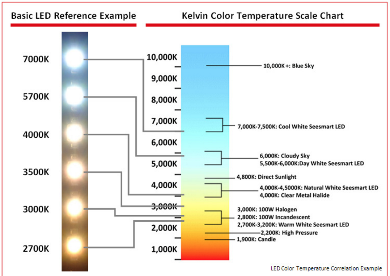
Remote color temperature change. Color temperature is often overlooked and misunderstood. In household lighting, generally a warmer source of light is much more pleasant. But with so many choices of lighting sources today (CFL’s, LED’s, Fluorescent tubes, Halogen, Incandescent) all of which come in different color temperatures, mistakes are made, or color temperature is completely overlooked. I found a great example of this looking at a residential building at night. Notice how some units are much cooler than others:
I would like to showcase this with my light by using an extremely cool LED source which will illuminate a warm lamp shade made out of muslin. The user will be able to peer into the lamp and see the cold source in contrast with the warm light it gives off via the fabric lamp shade.
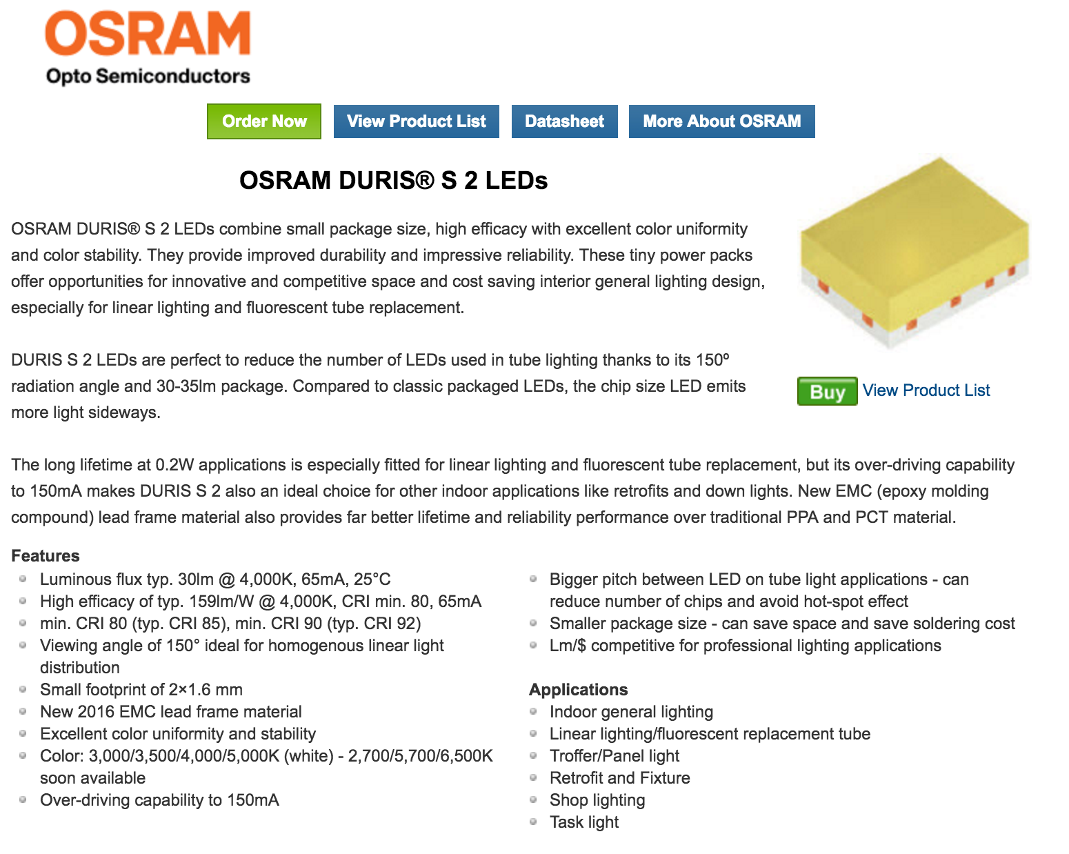
I began searching on mouser.com for products that met my parameters. I wanted the array to be a least 60 Lumens total and as efficient as possible. A new Osram LED product caught my eye – the Duris series 2:
At 2.9V they draw 65mA and produce around 30 Lumens. They can be overdriven to 150mA and have a 150 degree beam spread. They are very efficient and their CRI is very good as well.
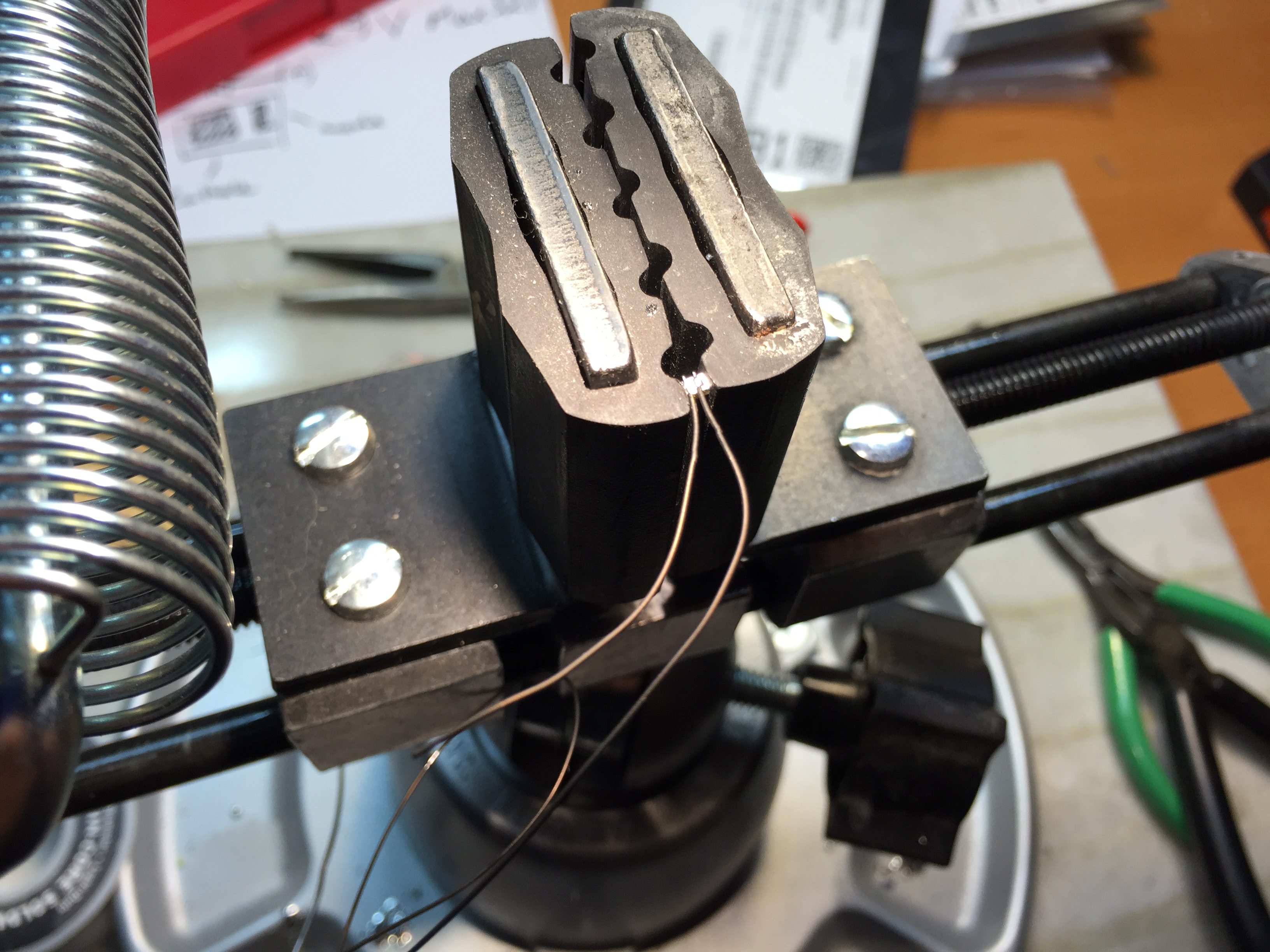
They are very tiny! Luckily my new panavise was able to hold one. I used a lot of flux and soldered two teflon insulated wires to each LED:
Here is the step by step process I have come up with for the charcoal electrodes thus far.
Step 1 is to solder a lead to the steel mesh. I use acid-core silver solder for this and a bigass 100W iron. I find acid core solder to be the only way to get a good soldered connection to steel. I used silver-bearing solder in hopes that it would have less of a chance of corroding (although the tin in the solder might end up negating that) Hopefully covering it with the pine rosin will help prevent extreme corrosion as well.
Next is heat up some rosin in a pan on low heat and sprinkle some cut up steel wool filings
Then drop the mesh onto the rosin and flip the mesh over. Then sprinkle some activated carbon over the mesh. Don’t let it sit for more than a few seconds before removing it from the heat.
Remove the electrode from the heat and place it on wax paper. Roll the carbon flat onto the mesh with heavy pressure.
Repeat for all three electrodes.
I then placed them briefly back onto the heat to help fuse everything together. I then removed the pan from the heat and let them cool down.
The saga continues with my charcoal electrode . . .
My next experiment was to try an make the water container itself into the anode for the battery. I started by forming a box out of stainless steel mesh:
I then combined activated carbon with pine sap in a 2:1 mixture over the stove, and formed it into the mesh box:
I was hopeful this would would work, but unfortunately its resistance was never lower than 30K Ohms between the mesh and any inside surface. I initially thought this might be due to the mixture being too thick, or the stainless steel mesh being too open.
Later on I realized that letting the heated pine rosin and the activated carbon sit for too long was causing the carbon to become oversaturated with the non-conductive rosin. Anywhere more than 30 seconds and the carbon starts to do what it does best – absorb!
As soon as the carbon becomes glossy, it has absorbed too much sap to conduct well enough for my battery.
Since I was having so much trouble getting a conductive mixture, I went back to experimenting with simple electrodes.
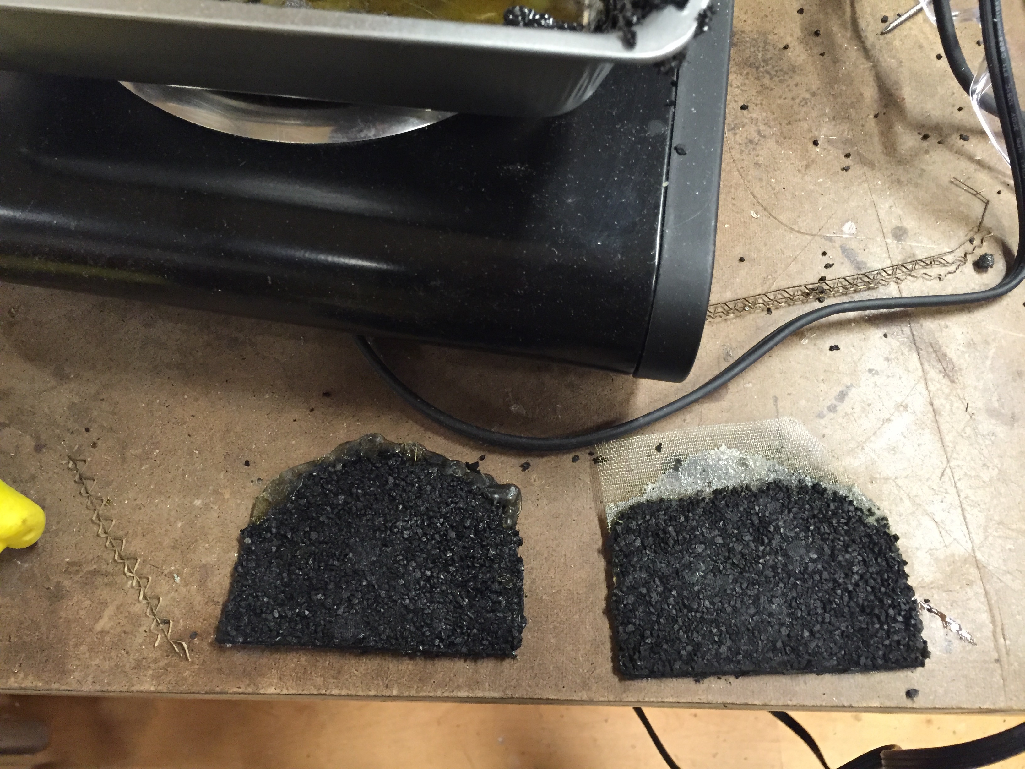
I went back to the tighter steel mesh and tried sprinkling the carbon over the sap instead of mixing them together:
This brought the resistance down significantly, but it was still to high:
At this point I was ready to give up completely on using the pine rosin. I decided to give it one more shot, and mix something conductive with the rosin.
I cut up some steel wool into small bits and mixed it with the melted rosin:
I put the steel mesh in first, then added the steel mesh and rosin:
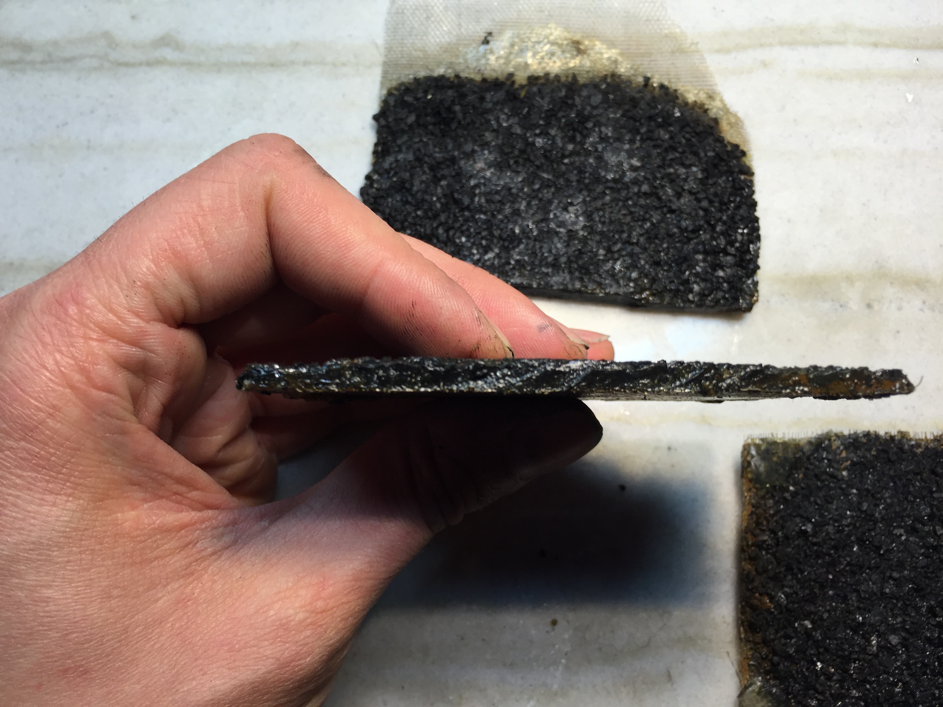
Then sprinkled the carbon on top. This time I removed the mesh almost immediately and pressed the carbon granules by rolling them with a pipe before the sap cooled back down:
Success! I was now getting closer to 10-30 Ohms between the back mesh and the charcoal.
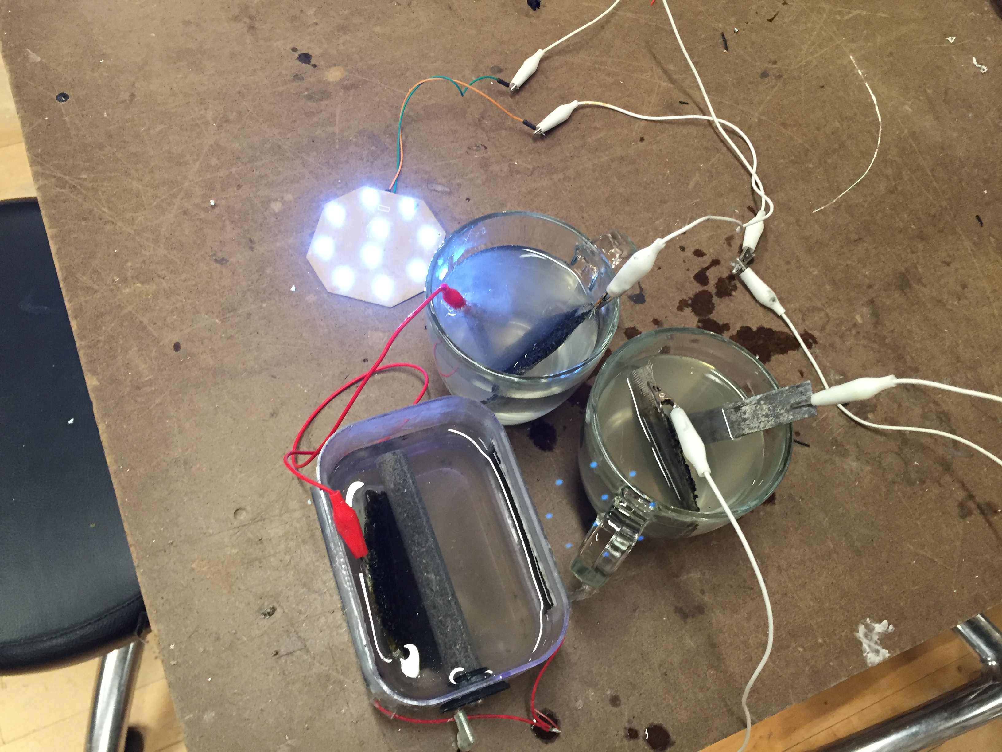
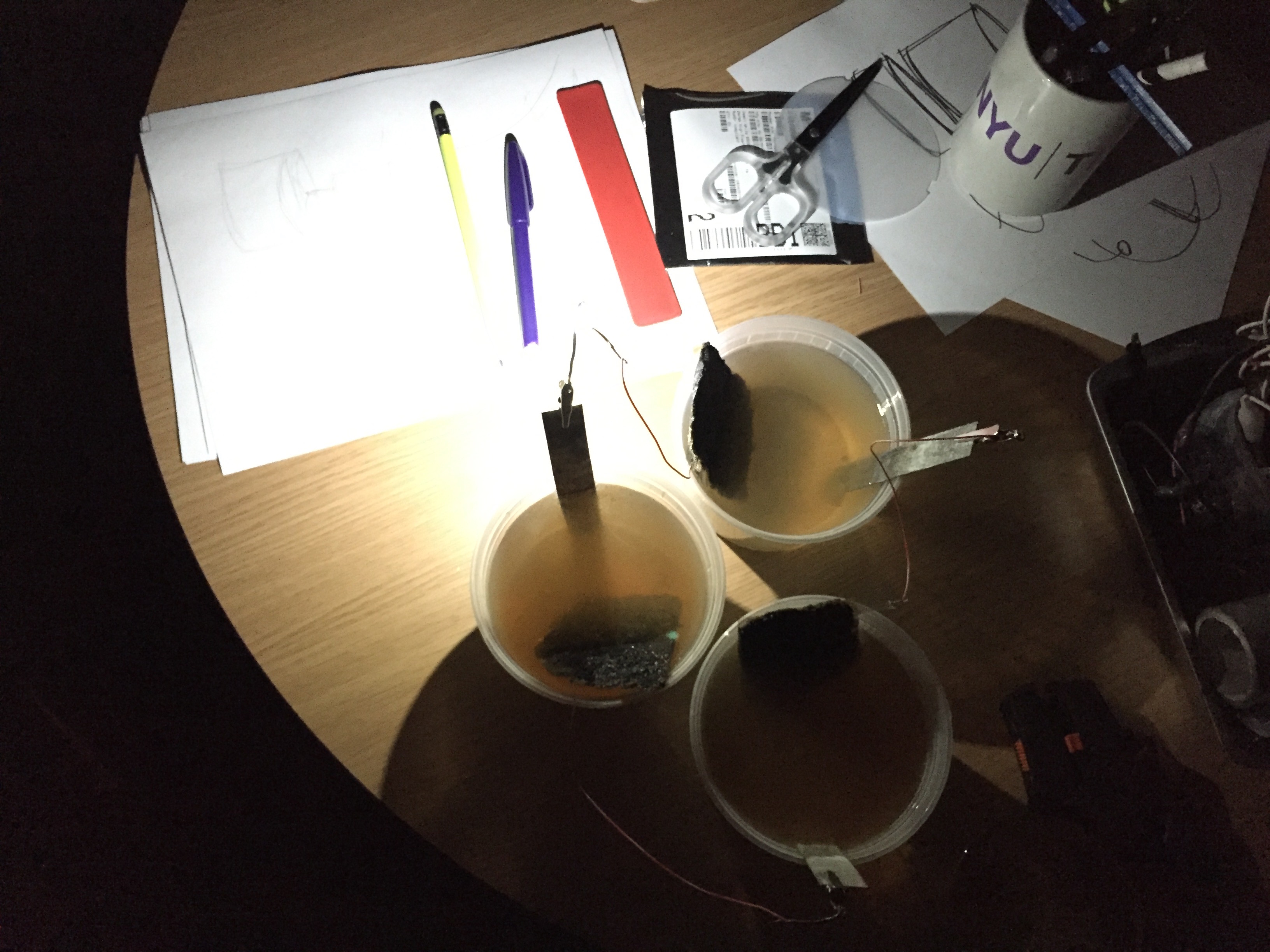
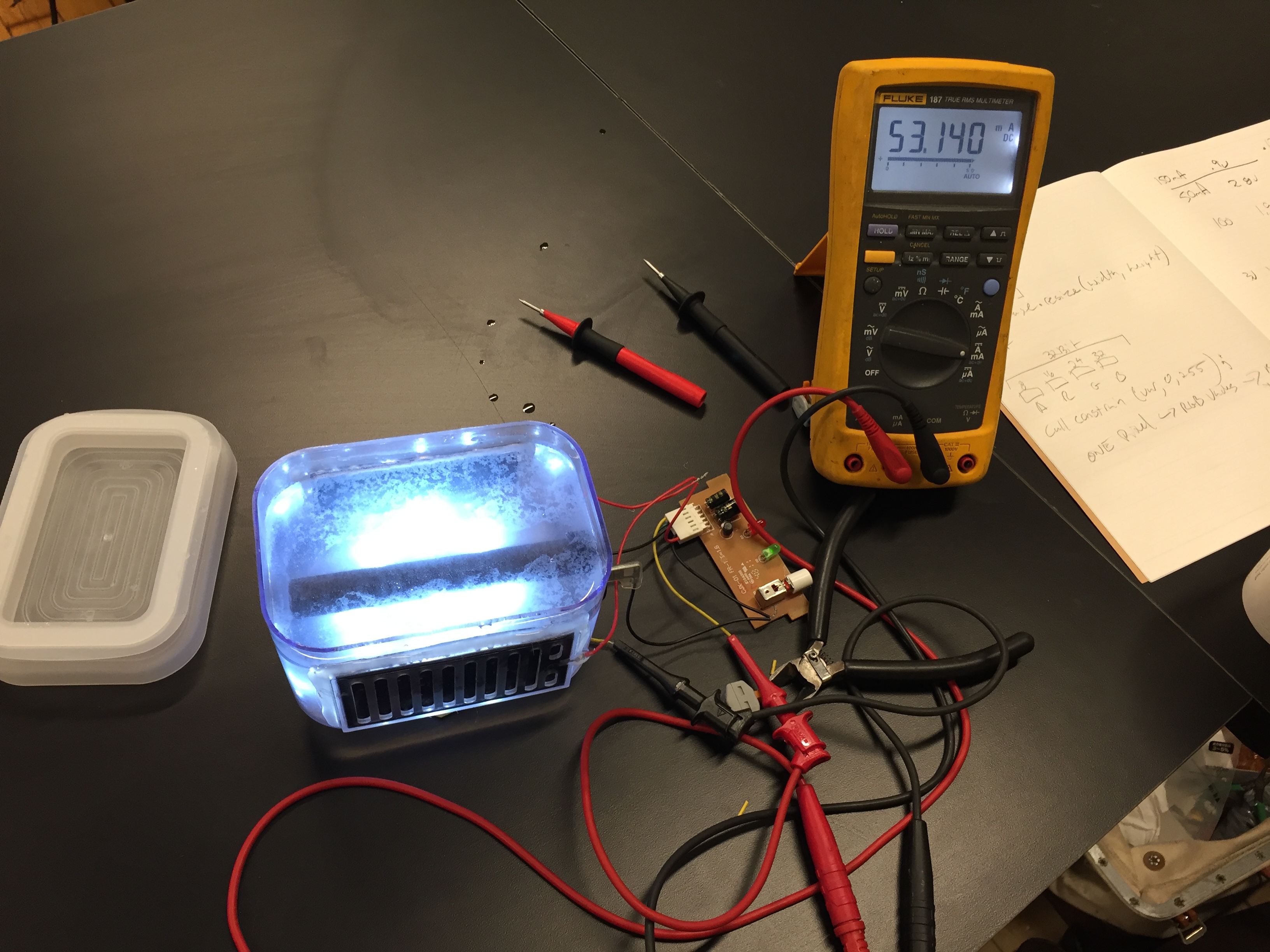
Finally I was able to power an LED array without any boost circuitry by using three separate cells wired in series with the LED’s. I am only using ten LEDs in parallel. No resistors or anything else.
I went home an tried the cells with the LEDs I ordered for the project (more on that later).
My batteries kept close to 100lumens of LEDs lit the whole night! The only byproduct was that the steel turned the water brown. I am hoping by covering the steel mesh with the sap completely that this effect will be diminished.
This week I began testing mixtures of carbon and the pine resin:
My first test uses activated carbon from an aquarium filter ground in a coffee grinder. I mixed this with melted pine resin. The resin starts to liquify with a small amount of heat. A hair dryer will cause it to bubble. I mixed in the carbon dust and spread the hot mixture on a stainless steel mesh.
The result was an electrode with too high of a resistance. Somewhere in the neighborhood of 25KOhms between the surface of the mix and the steel mesh.
I then found mixing full carbon granules into the pine sap resulted in a lower resistance. I went ahead and tested several mixtures of pine sap and carbon. I also tried some graphite dust mixed with the sap, and two commercial carbon based paints applied to steel mesh as well. Here are the two products:
I tested each electrodes resistance by pressing them down onto a copper plate wired to one side of my multimeter, and wired the other side to the stainless steel mesh in each sample. I took care to make sure the mesh did not contact the copper plate directly.
The large granules mixed with the pine sap seem to perform pretty well. My next step is to build an electrode with a larger surface area in order to increase the voltage and current output. I might try building the water container entirely out of the carbon electrode. I also want to try and eliminate the steel mesh. Im not sure if the resistance is low enough across mixture to just attach a lead on one side without an added conductive plane.
An important part of my salt water cell is its carbon electrode. Up until now I have been using a commercially made electrode. Where the magnesium electrode is just a simple rod, the carbon electrode is a little more complicated. It is made up of some form of carbon or graphite, a binding agent, and some form of mesh to hold it in place. I want to be able use regular charcoal from a fire for my carbon electrode, and some non-toxic binding agent. In order to produce consistent results for now, I started with some activated carbon filters for aquariums. After a few minutes in the coffee grinder, I had a fine, and very messy carbon powder. It conductivity was around 130 Ohms which is similar to the commercial electrode.
I mixed the carbon powder with some clear gel kraft glue. I added rubbing alcohol to thin it out temporarily as well.
I then spread the mix over a stainless steel mesh and clamped it in my vice:
It works!
I was amazed to see the magnesium start to fizz when I dropped it in. The only issue with it is that the kraft glue does not hold up underwater for very long. I was a little stumped since I wanted to use a natural glue for the binding agent, but most are water-based. I started researching natural glues that were waterproof. There were many interesting glues out there.
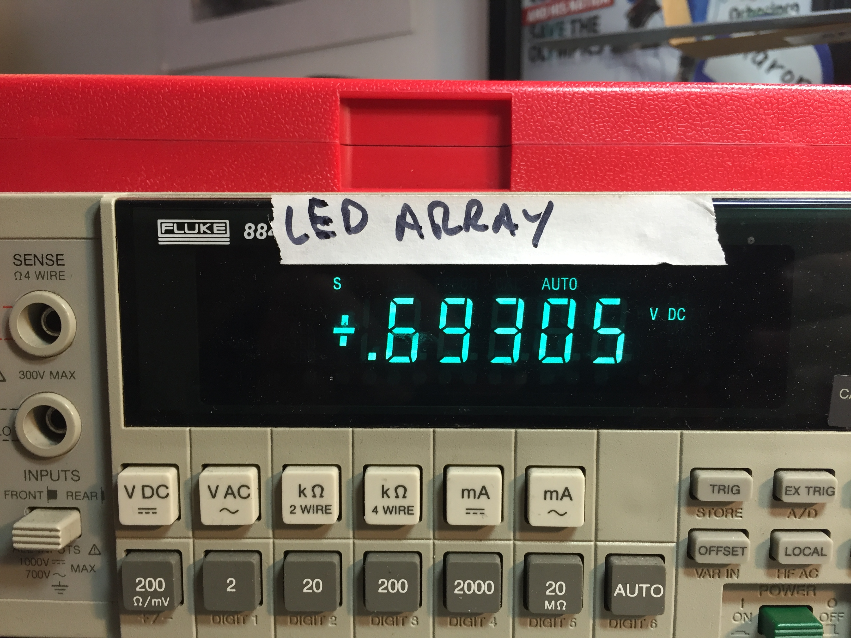
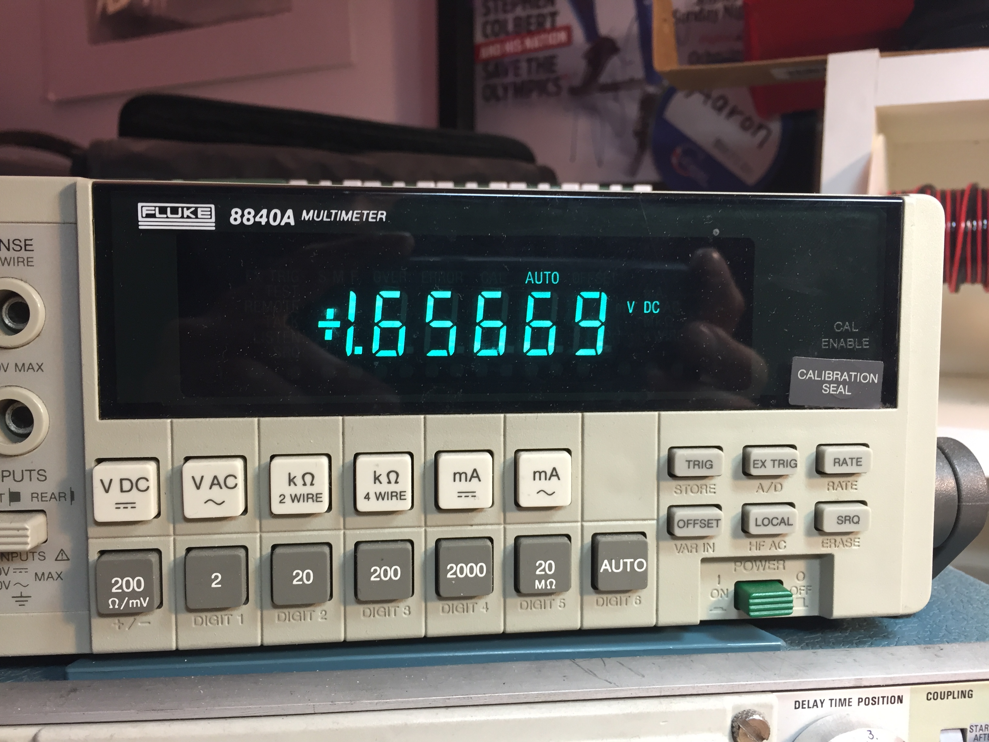
Here is the battery ratings with my charcoal electrode:
One recipe that caught my eye was pine sap glue. The recipe I came across after a quick google search can be found here:
Surprisingly the only ingredient other than pine sap is charcoal. I’m now wondering if I can produce an all natural electrode by increasing the amount of charcoal called for? I ordered some pine resin off amazon.com to start experimenting with.
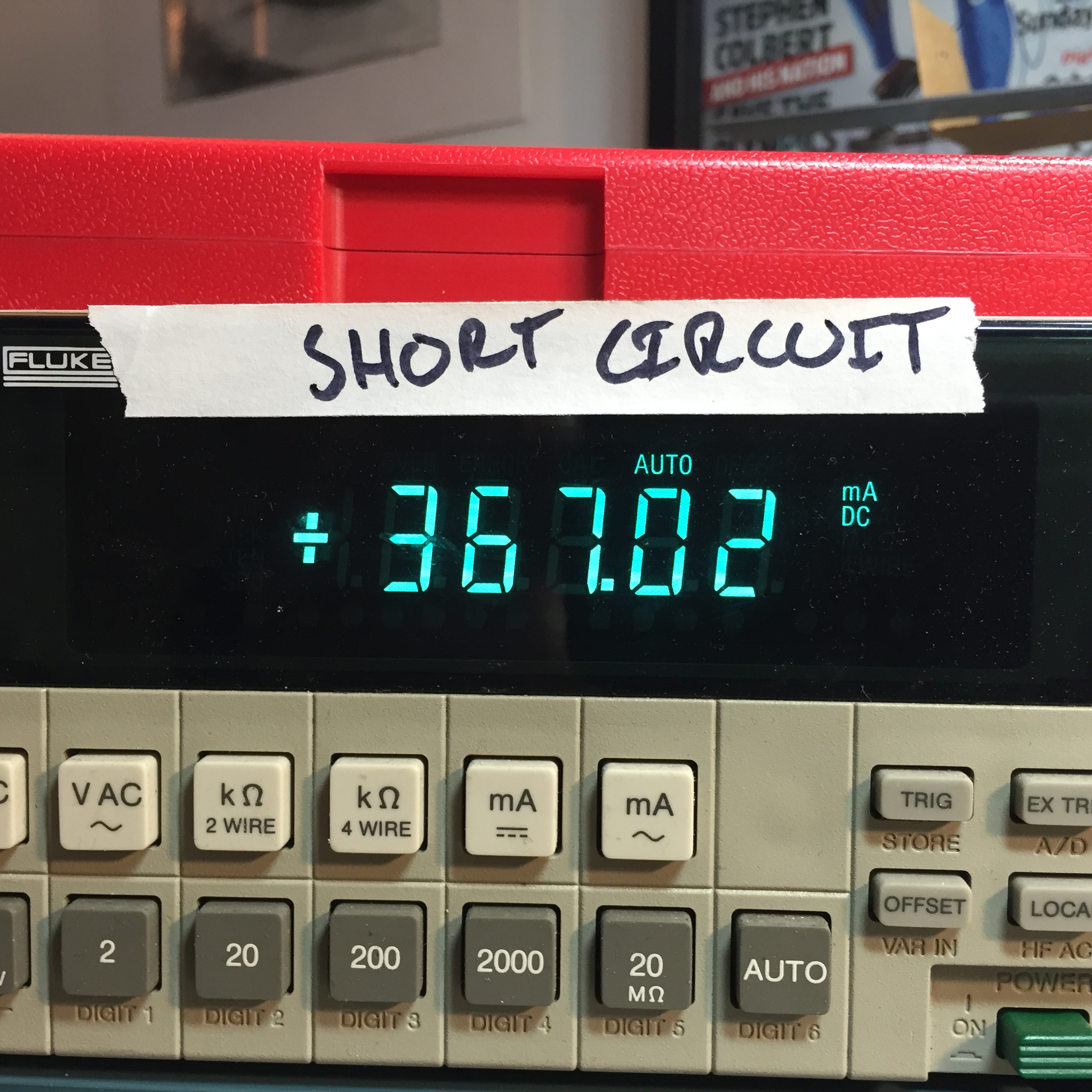
The rest of my electrode materials have arrived. I have not tried all of them, but I had immediate success with a magnesium rod and two sheets of activated carbon. The battery is drawing 500mA when short circuited!
I attached my new battery to a DC/DC boost circuit and an LED array. Both were taken out of a garden solar light. Most garden solar lights use a single 1.2v NiMh cell, which is nearby to the 1.3V that my battery is producing when the LEDs and boost circuit are connected. To the left you can see how the circuit is pulsing the battery input on my oscilloscope:
The battery will work with many different solutions. Even old wine! (although not as well):
An interesting side effect is that the battery will bubble when a load is applied. I might find a way to incorporate this into the final design.
While I wait for all my electrode materials to arrive, I began my testing of the salt water battery system with what I have available.
My first test uses a carbon rod and a zinc plate. The result was a very small voltage; even after putting two cells in series this was only enough to light a single red LED:
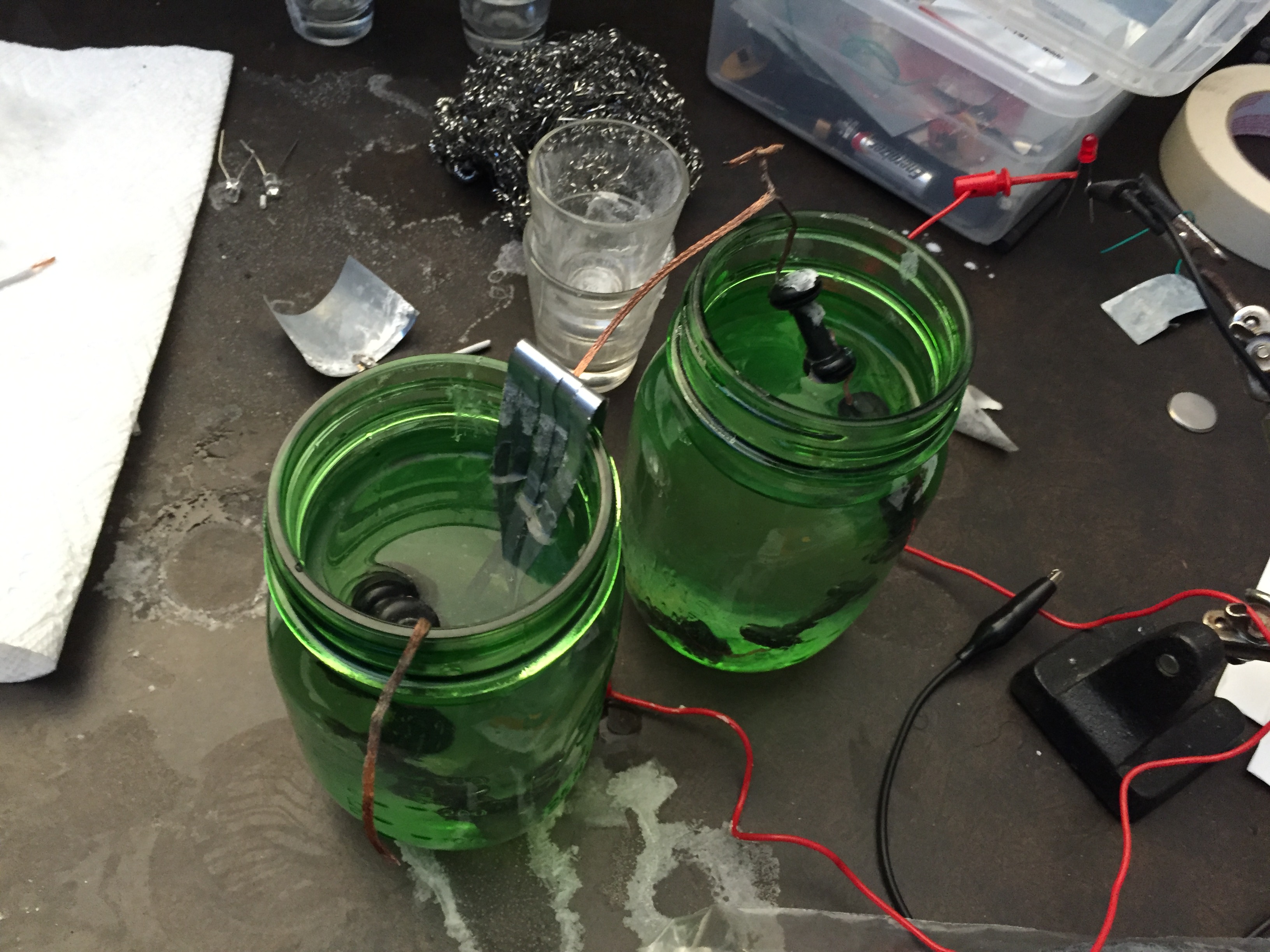
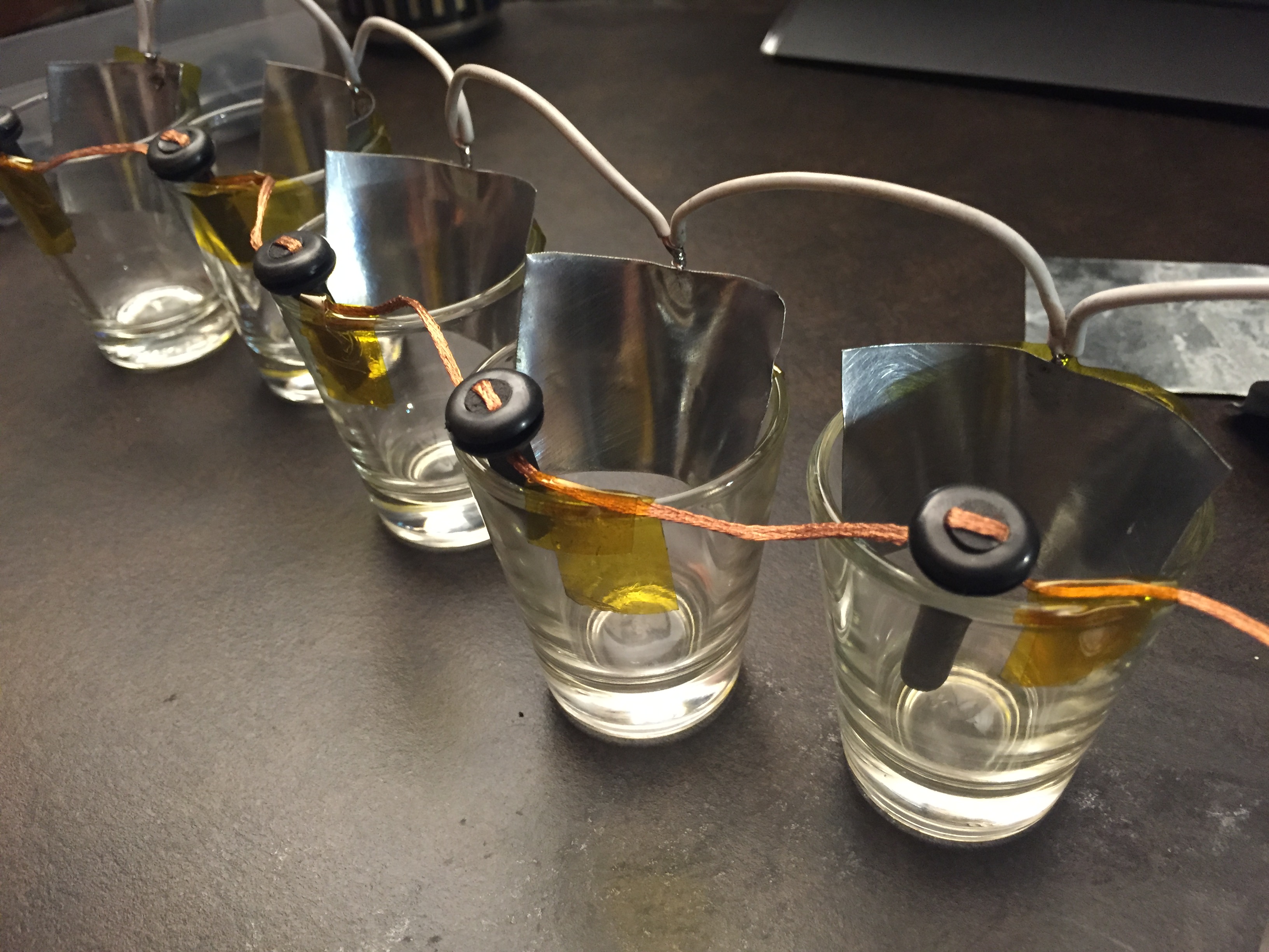
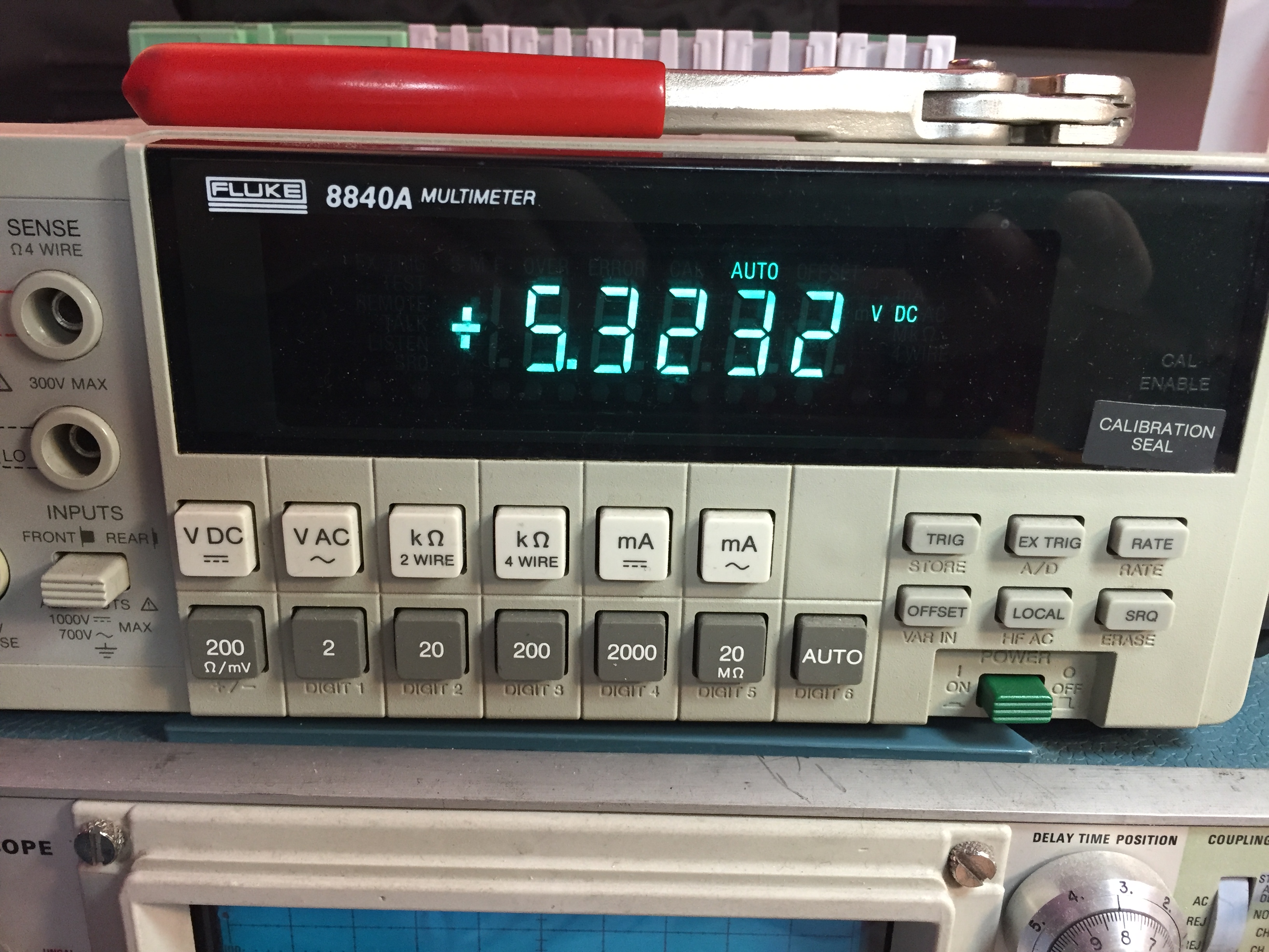
I then tried to increase the voltage by dividing my system into eight cells in series:
This still only provided a few milliamps at 5.3volts
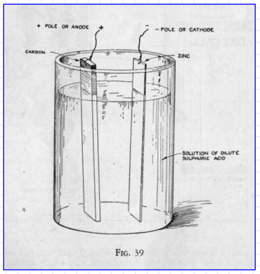
A salt water battery is a wet-cell battery that uses salt water as its electrolyte. Normally wet-cell batteries use acids for their electrolyte. Car batteries use sulfuric acid – nasty stuff. The goal of this project is to to use safer materials than those found in normal batteries. Cadmium, Sulfuric Acid, Potassium hydroxide are all not good for the environment or for people.
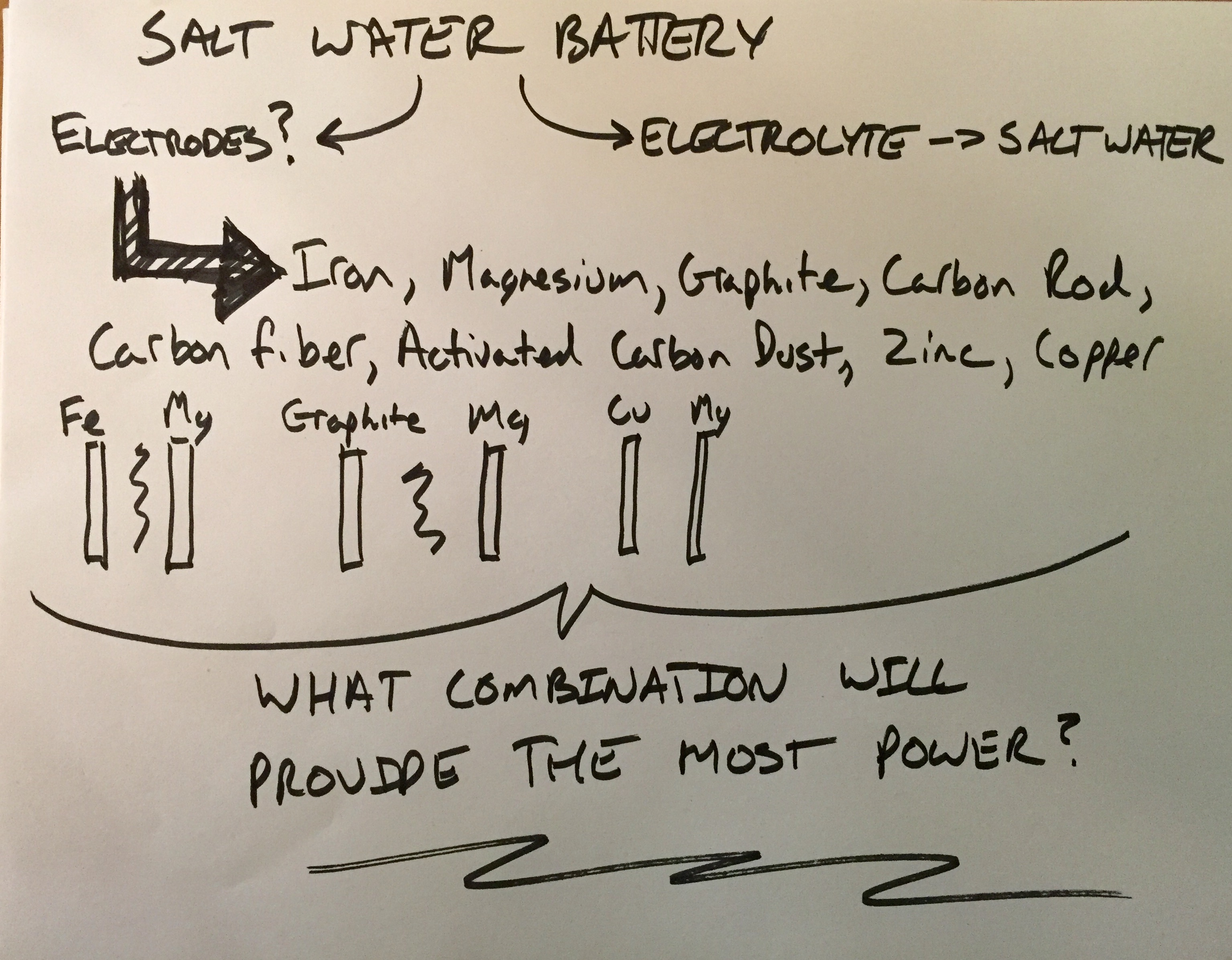
My research begins with trying for find out what the two electrodes should be made of to provide the most power out of the saline solution I have chosen. I have decided to work with salt water that has a similar salinity to sea water. I feel using elements and liquids that are commonplace will help people best understand what the battery is made up of. Lead and acids have nasty connotations.
The salinity of seawater according to wikipedia is around 3.5%
Finding information on what the best electrodes to use has proven to be much more difficult to weed through via research on the internet. Let down by hours of weeding through eco-friendly-energy-snake-oil, I decided to order samples of common electrode materials and test them in different combinations myself.
Dream – My dream is to create a personal light that runs via a natural battery and includes a level of interaction that brings with it excitement and enjoyment to its owner. The goal of this light is for it to be an object that comes closer to eco-friendly than its plug-in counterparts. Additionally it should be more than just a utility ‘lantern’ source of light. I like to think of lighting as universal to everyone who can see. I want to design a light that can be used by any person anywhere on the planet.
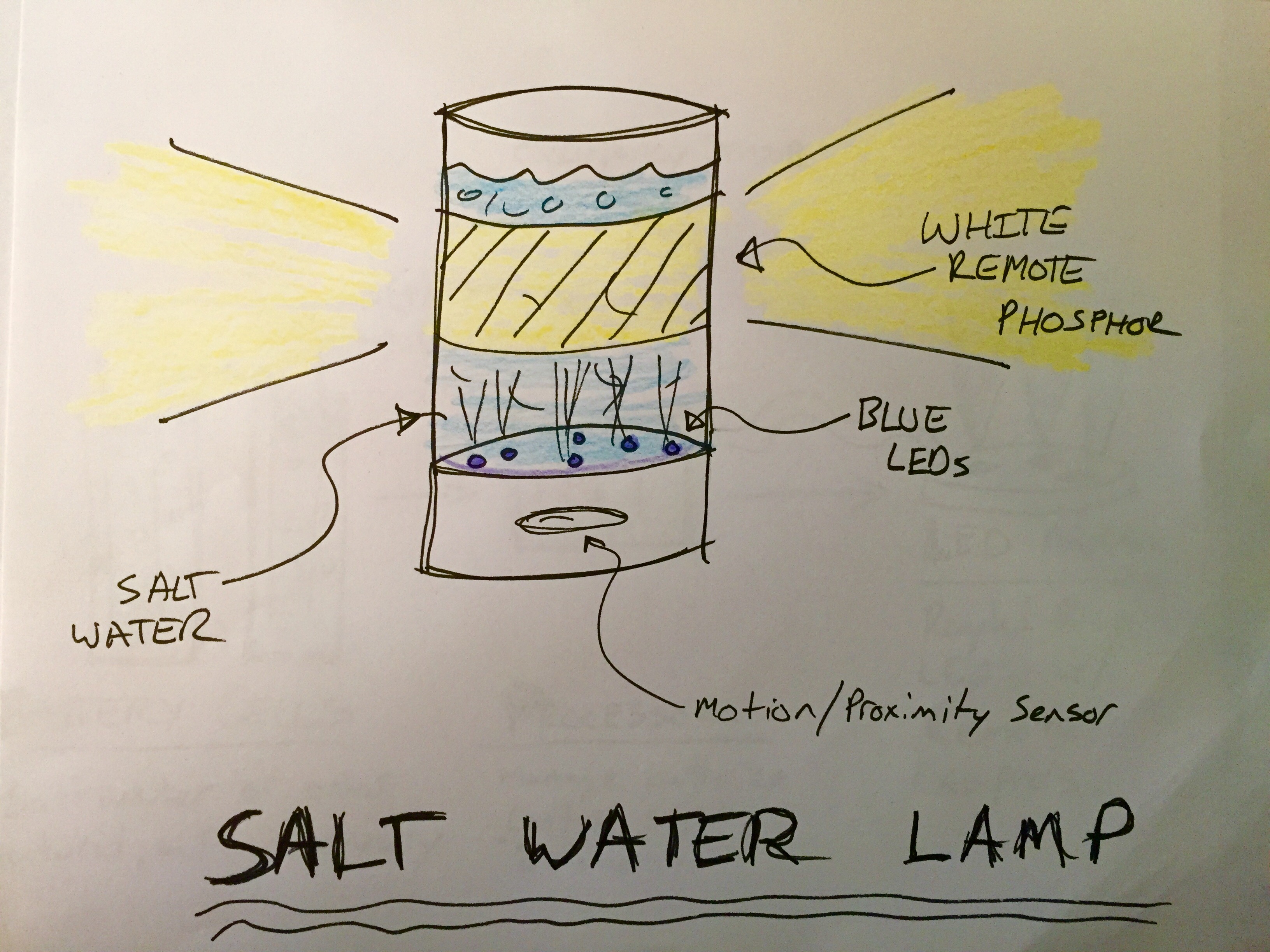
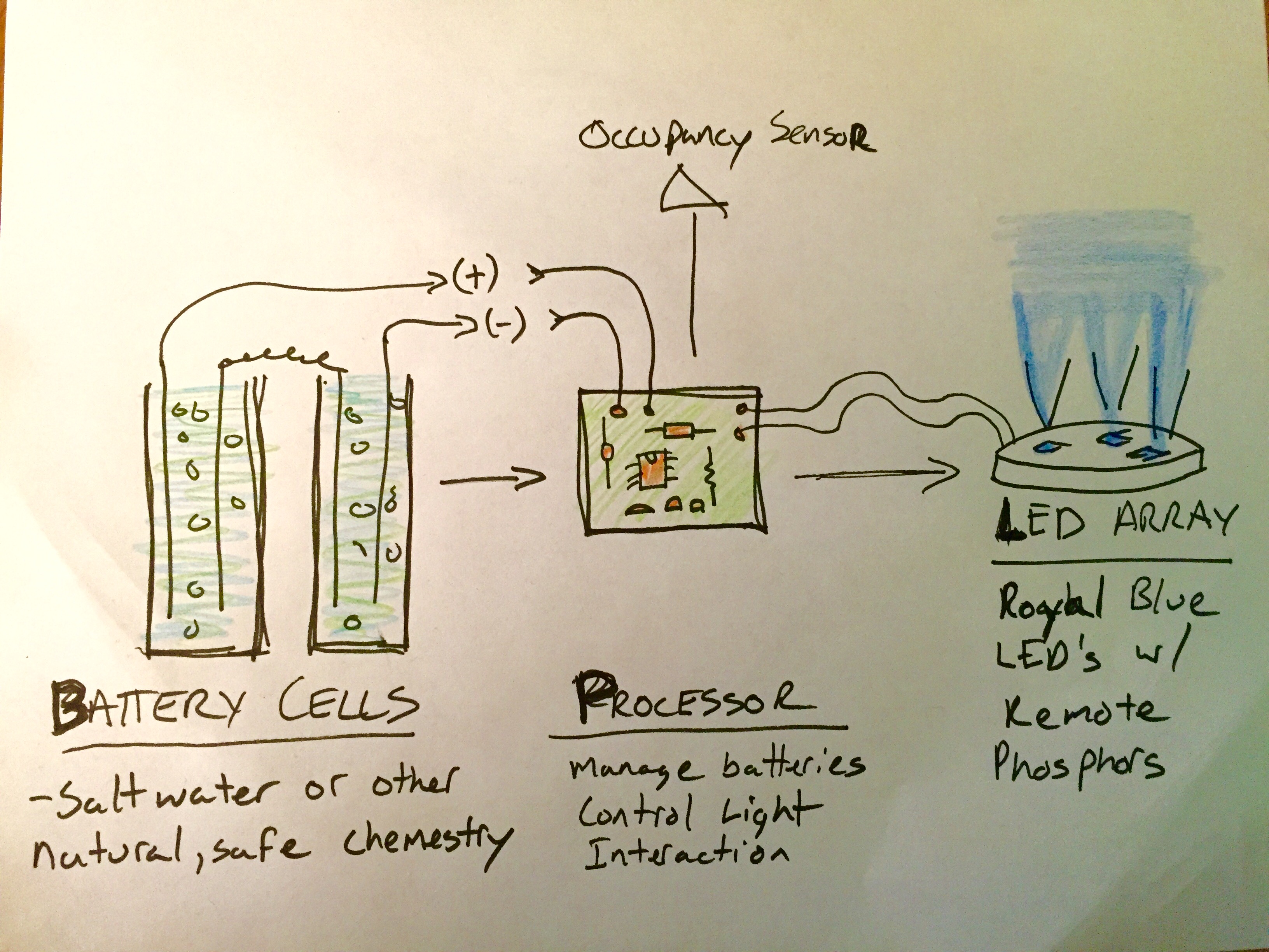
Vision – I would like this light to be powered by an electrochemical source that is less harmful to the environment than typical batteries. A simple salt-water battery or something organic in nature would be ideal. That materials that make up the enclosure should be more eco-friendly than just plastic as well. The light itself should be at least bright enough to allow its owner to read with. I have been experimenting with remote-phosphor LED lighting, and I think using blue LED’s to light a white phosphor plane would be a novel addition to the project.
Goal – This semester at ITP I would like to build a working light that operates via an organic battery. The battery will power an LED array as well as a microcontroller that will adapt the output of the LED array in terms of mood and intensity for the user based on readings from a proximity sensor.
Plan – (35% chance things go this way)
2/10 – Research saltwater batteries and useable electrodes
2/17 – Order and test different electrode materials to find the best combination
2/24 – fine tune battery
3/2 – fine tune battery and DC/DC boost circuit, research high efficiency LED’s
3/9 – create LED array, research low energy atmel MCU’s
3/23 – Decide on proximity sensor, proof with chosen MCU


