3rd Assignment – Digital and Analog Labs

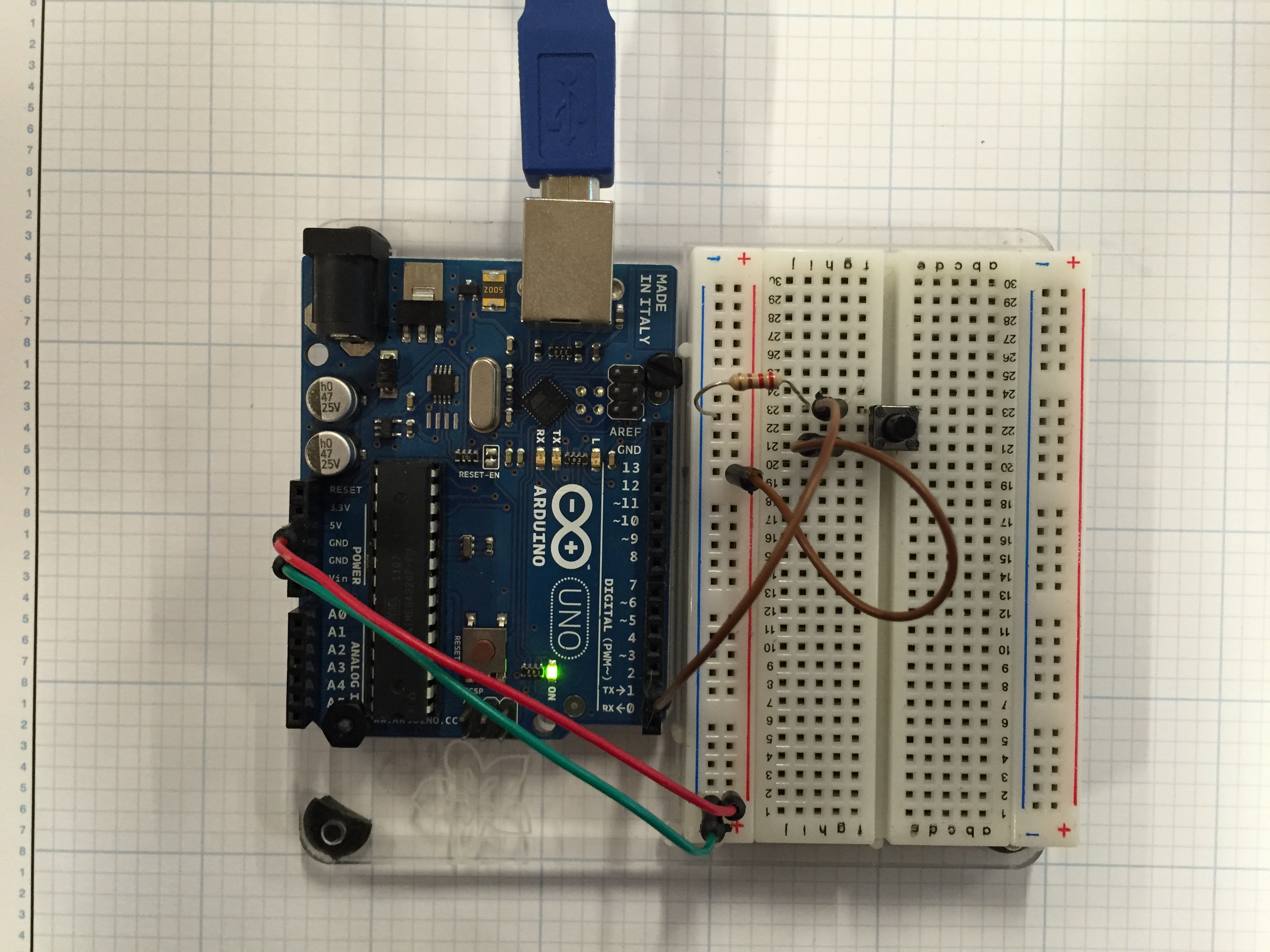
This week we started to use the Arduino to input and output analog signals.

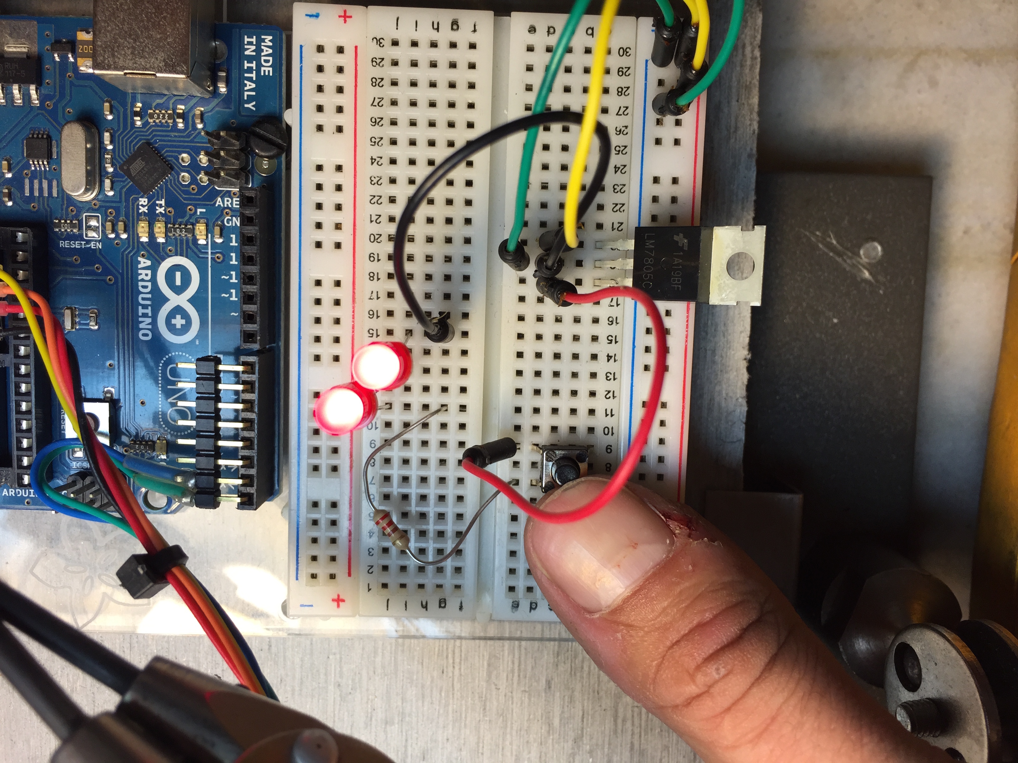
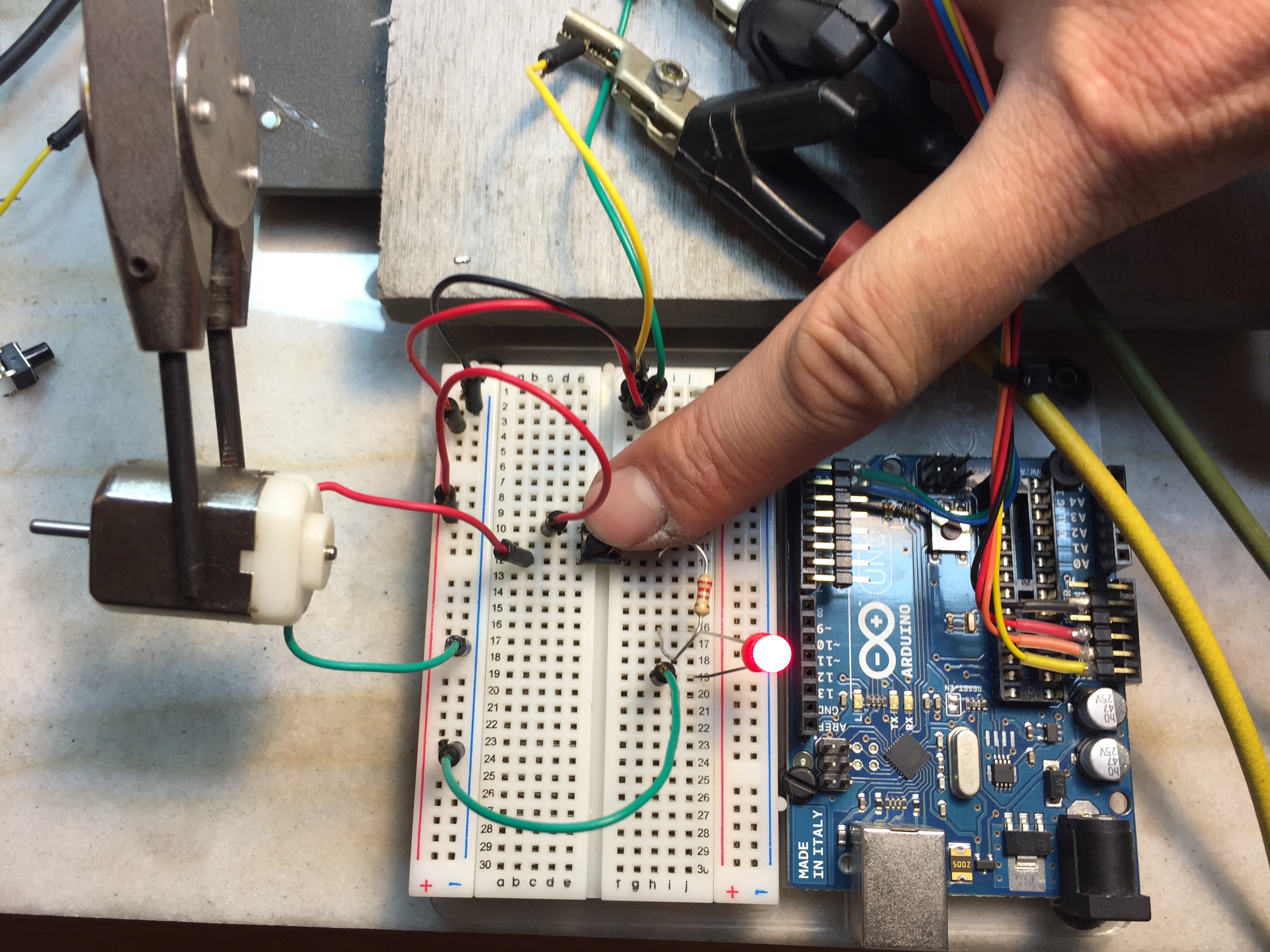
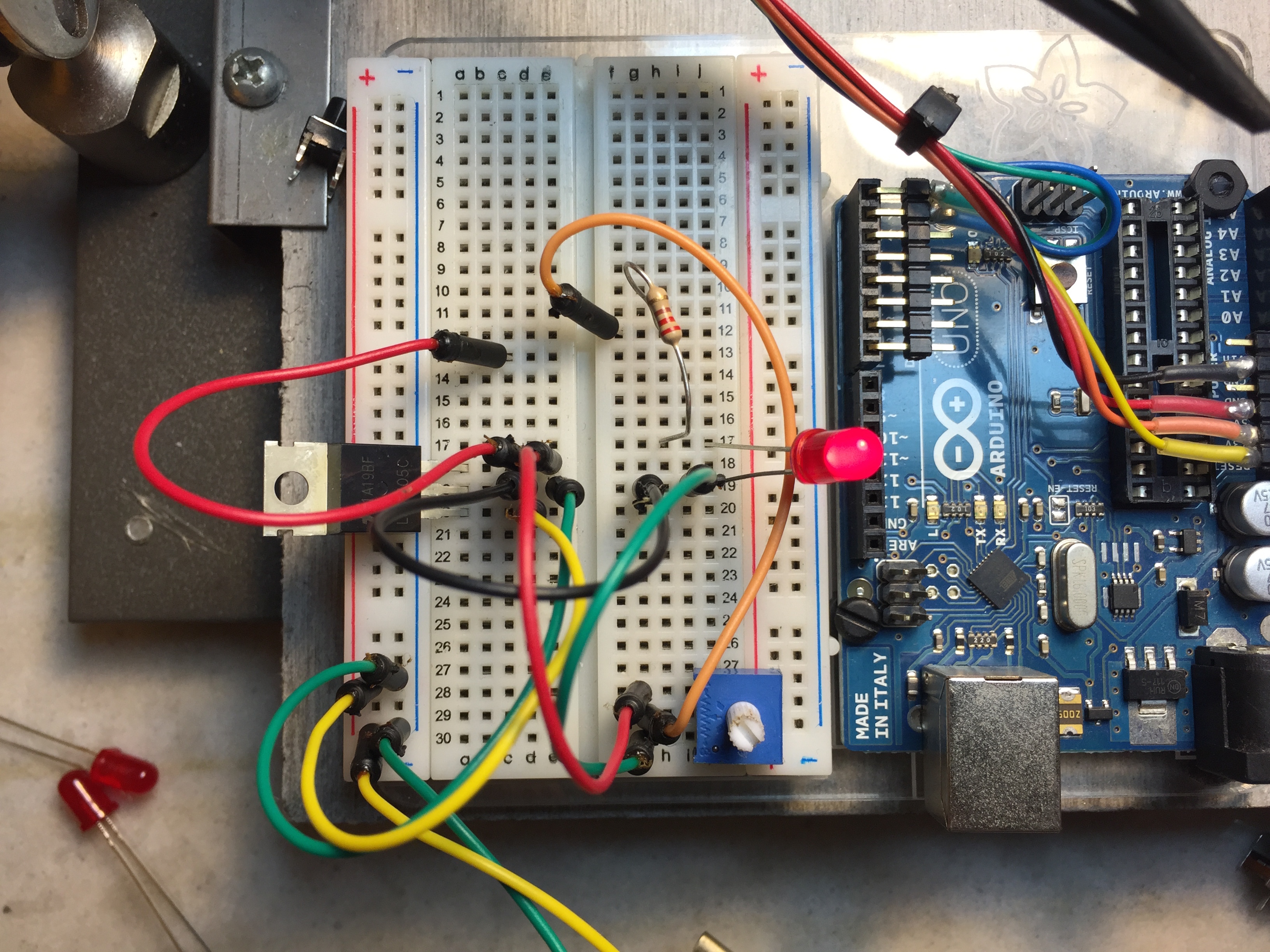
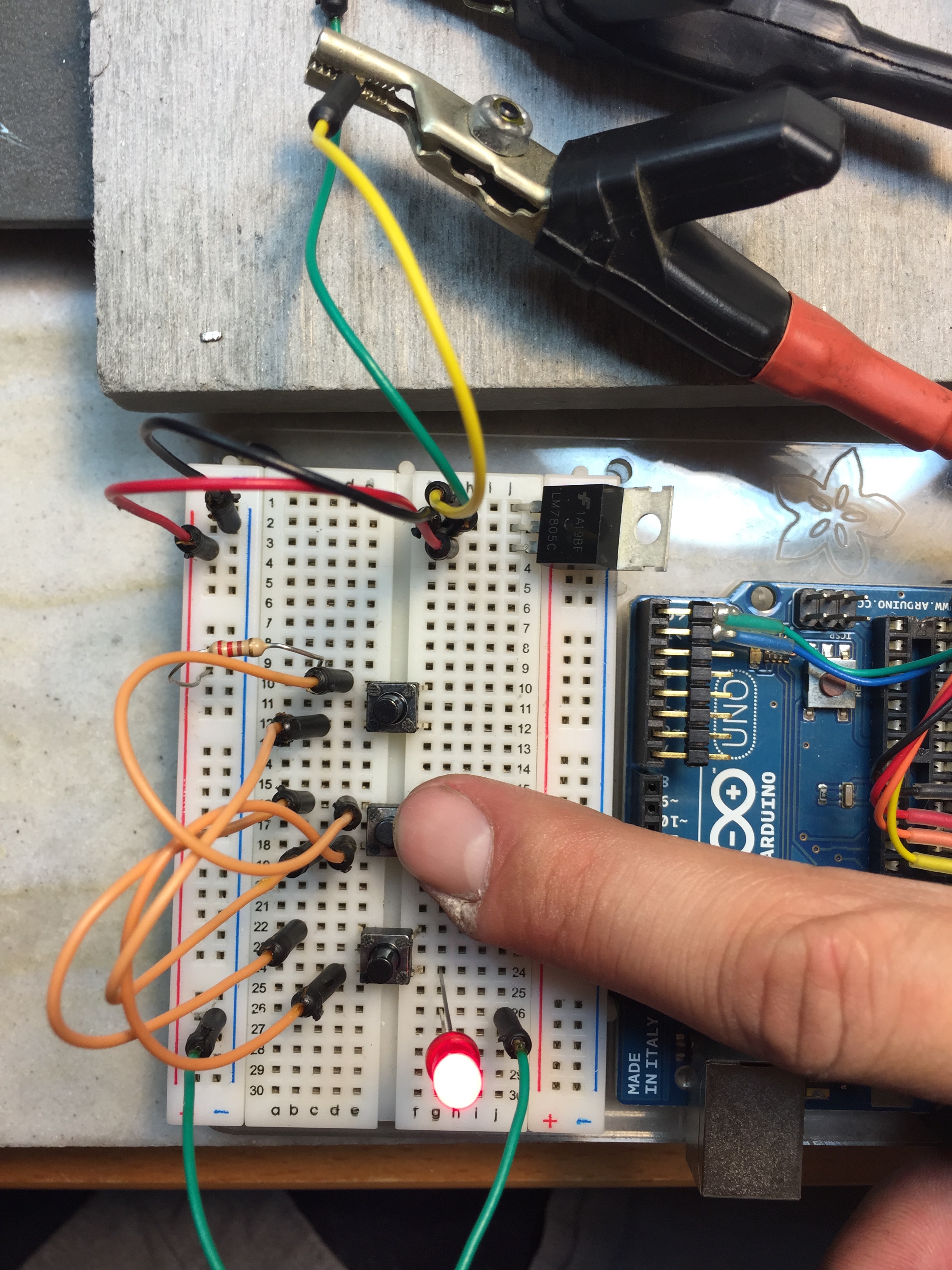
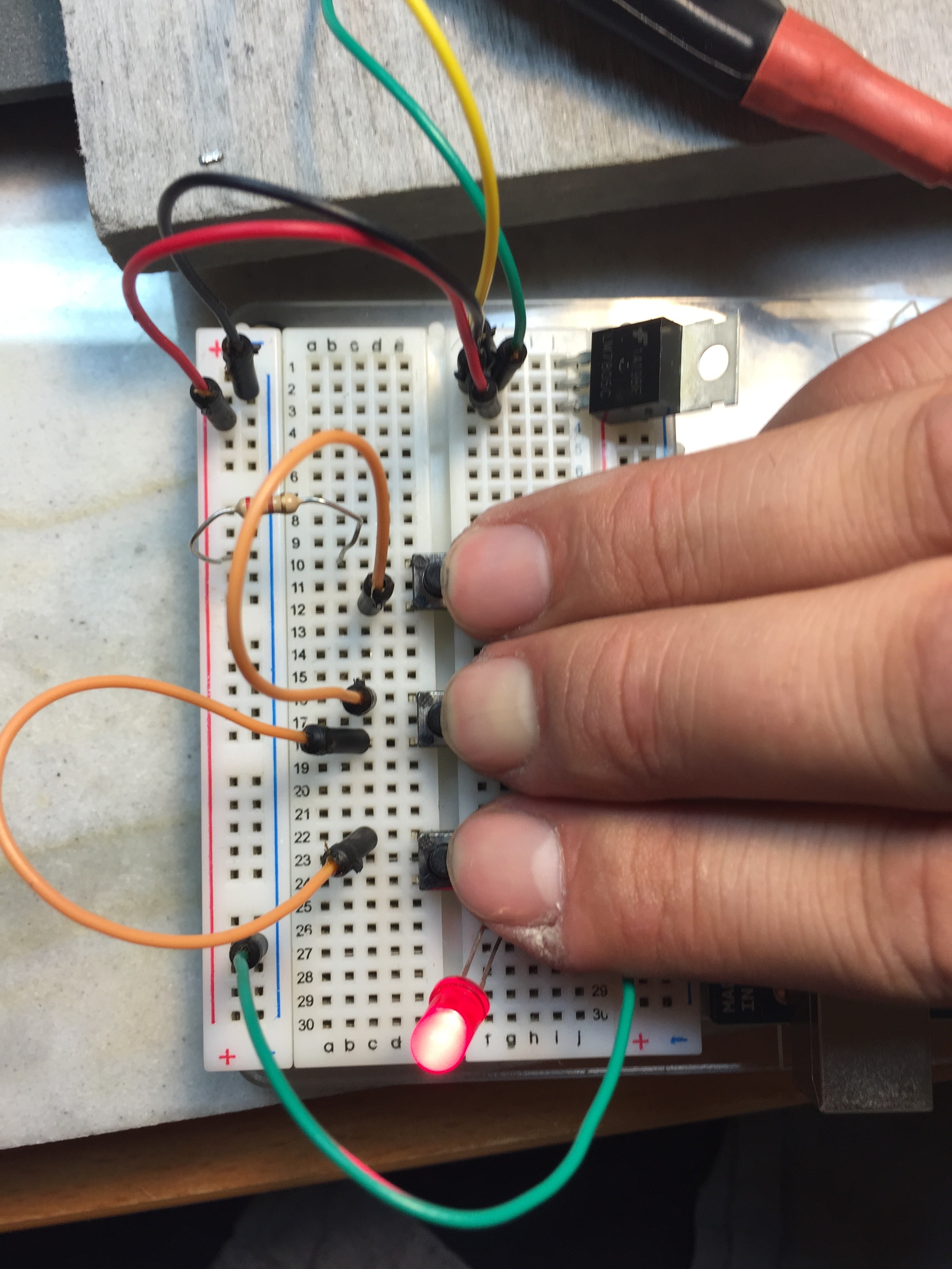
Beginning with a simple pushbutton to turn on an LED:

button_pin2

void setup() {
pinMode(2, INPUT); // set the switch pin to be an input
pinMode(3, OUTPUT); // set the yellow LED pin to be an output
pinMode(4, OUTPUT); // set the red LED pin to be an output
}
void loop() {
// read the switch input:
if (digitalRead(2) == HIGH) {
// if the switch is closed:
digitalWrite(3, HIGH); // turn on the yellow LED
digitalWrite(4, LOW); // turn off the red LED
}
else {
// if the switch is open:
digitalWrite(3, LOW); // turn off the yellow LED
digitalWrite(4, HIGH); // turn on the red LED
}
}

Next we worked with analog inputs:


const int ledPin = 9; // pin that the LED is attached to
int analogValue = 0; // value read from the pot
int brightness = 0; // PWM pin that the LED is on.
void setup() {
// initialize serial communications at 9600 bps:
Serial.begin(9600);
// declare the led pin as an output:
pinMode(ledPin, OUTPUT);
}
void loop() {
analogValue = analogRead(A0); // read the pot value
brightness = analogValue /4; //divide by 4 to fit in a byte
analogWrite(ledPin, brightness); // PWM the LED with the brightness value
Serial.println(brightness); // print the brightness value back to the serial monitor
}

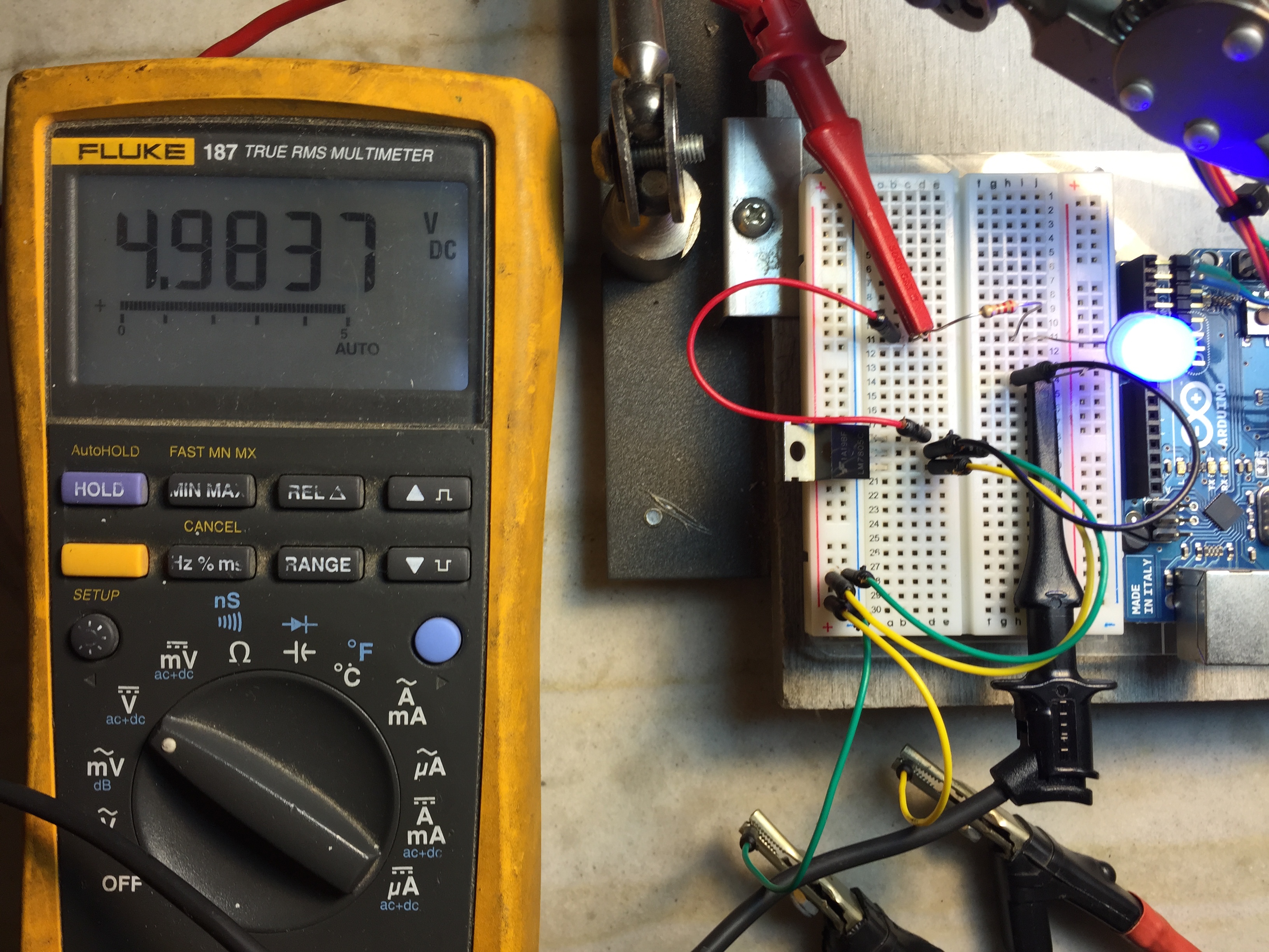
Here is the code outputting to a potentiometer:

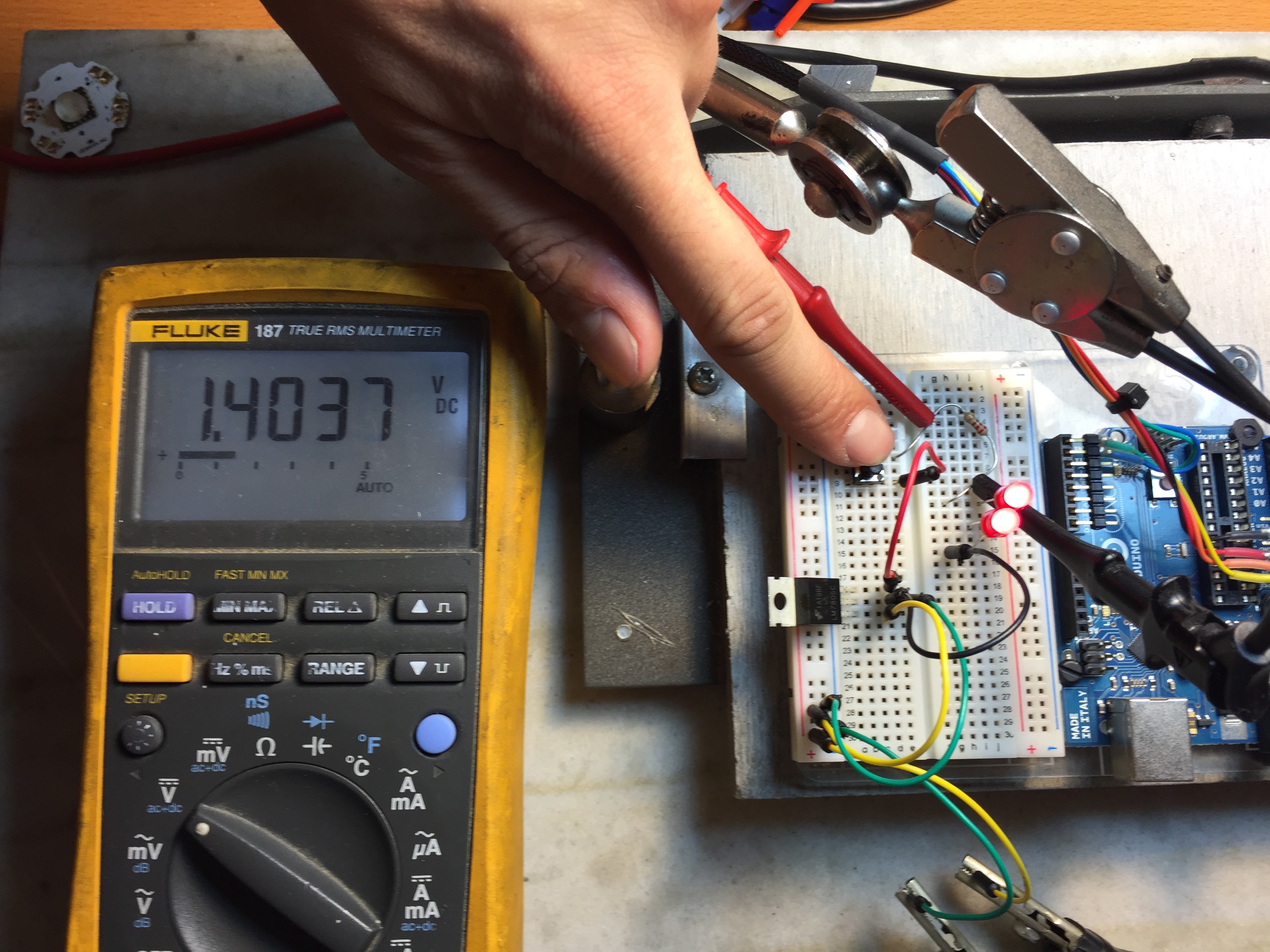
And here it is with a CdS Photoresistor:


Finally I decided to work a little with outputting pulse width modulation to an LED, controlled via a sliding pot. Here is the simple code:


const int potPin = A0;
const int ledPin = 3;


int sensor = 0;
int output = 0;


void setup() {
}


void loop() {
sensor = analogRead(potPin);
output = map(sensor, 0, 1023, 0, 255);
analogWrite(ledPin, output);
}

Here is what it looks like on my oscilloscope while “dimming” 🙂

2nd Assignment – fun with very simple circuits

This week we went over buttons/switches, LED’s, and resistors. We also plugged in a 7805 5VDC voltage regulator.

Starting with the 7805:

volt across led

Looks like its doing its job! The meter is measuring voltage across the blue LED and the 220Ohm 1/8 watt resistor.

Up next we have two red LED’s in series with a 220Ohm resistor:

2 led series

2 led series volt across r

The 220Ohm resistor is drawing 1.4VDC.

Next up we have three red LED’s in parallel. I have lifted the left LED’s anode and put my amp meter in parallel. These sissy LED’s are only drawing 1.4mA.

Here we have an LED and a little motor in parallel:

motor led para

And finally a voltage divider made with a 10Kohm potentiometer:

volt divider

And now some switches! Not sure which one to use 🙂

switches

Here are three normally-open push buttons in parallel:

para switch

And here they are in series:

series sw


For my switch project I decided to have some fun with a 40watt RGBW LED. I stated by mounting it to an old pentium III heatsink, with some thermal compound in between:

led hs

Next I went to the data sheet. I’ve had this thing for four years . . . luckily mouser saves your purchase orders 🙂

I found the forward voltage ratings and decided to run this thing at 12VDC. The Green diodes forward voltage starts at 12.8V, but Im sure it’ll look fine at 12V. These are some big numbers to be seen for an LED. This LED certainly must be a package containing several dies per color. . .

Screen Shot 2015-09-16 at 1.00.28 AM

Even my awful math skills can figure this out 🙂

FullSizeRender 2

Next we add some switches:

led wired

Here is the final product!

led purple

Looks like we are drawing a happy healthy 520mA with a 12VDC input. For the white, the closest high power resistor I had was 3.9ohms instead of the 2.14ohms I calculated.

IMG_0841

This guy is painfully bright at 12VDC, so I think for class I will stick with a 9V battery.

led blu

1st Assignment – What is physical interaction?

Physical interaction to me is when a human projects an action onto a computer or device, and that action is used to choose a response by said device intelligently. Interaction is not a direct translation, but rather an interpretation of an action and the reaction that follows. In my opinion, good physical interaction (in terms of technology) comes when a device has the capacity to understand slight nuances in a users action, and can respond to them quickly and in exactly the way the user had hoped for . . . maybe without even knowing the devices response was what they wanted.

A good example of technology that is not interactive would be forms of transducers. A simple two-way radio that is converting sound into radio waves is not interactive.