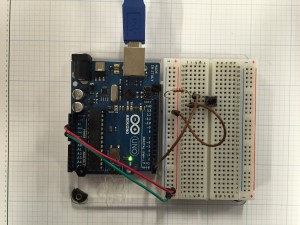
This week we started to use the Arduino to input and output analog signals.
Beginning with a simple pushbutton to turn on an LED:
 void setup() {

pinMode(2, INPUT); // set the switch pin to be an input

pinMode(3, OUTPUT); // set the yellow LED pin to be an output

pinMode(4, OUTPUT); // set the red LED pin to be an output

}

void loop() {

// read the switch input:

if (digitalRead(2) == HIGH) {

// if the switch is closed:

digitalWrite(3, HIGH); // turn on the yellow LED

digitalWrite(4, LOW); // turn off the red LED

}

else {

// if the switch is open:

digitalWrite(3, LOW); // turn off the yellow LED

digitalWrite(4, HIGH); // turn on the red LED

}

}
Next we worked with analog inputs:
const int ledPin = 9; // pin that the LED is attached to

int analogValue = 0; // value read from the pot

int brightness = 0; // PWM pin that the LED is on.

void setup() {

// initialize serial communications at 9600 bps:

Serial.begin(9600);

// declare the led pin as an output:

pinMode(ledPin, OUTPUT);

}

void loop() {

analogValue = analogRead(A0); // read the pot value

brightness = analogValue /4; //divide by 4 to fit in a byte

analogWrite(ledPin, brightness); // PWM the LED with the brightness value

Serial.println(brightness); // print the brightness value back to the serial monitor

}
Here is the code outputting to a potentiometer:
And here it is with a CdS Photoresistor:
Finally I decided to work a little with outputting pulse width modulation to an LED, controlled via a sliding pot. Here is the simple code:
const int potPin = A0;

const int ledPin = 3;
int sensor = 0;

int output = 0;
void setup() {

}
void loop() {

sensor = analogRead(potPin);

output = map(sensor, 0, 1023, 0, 255);

analogWrite(ledPin, output);

}
Here is what it looks like on my oscilloscope while “dimming” 🙂
