For my final project I would like to build a miniature yoked moving light similar to the ones used in concerts. As a lighting designer I am always using these fixtures, however smaller ones are very hard to come by.
https://www.youtube.com/watch?v=EeEkLHayHxA
I would like to build the electronic control of my fixture as simply as possible, so that I can focus on the mechanics.
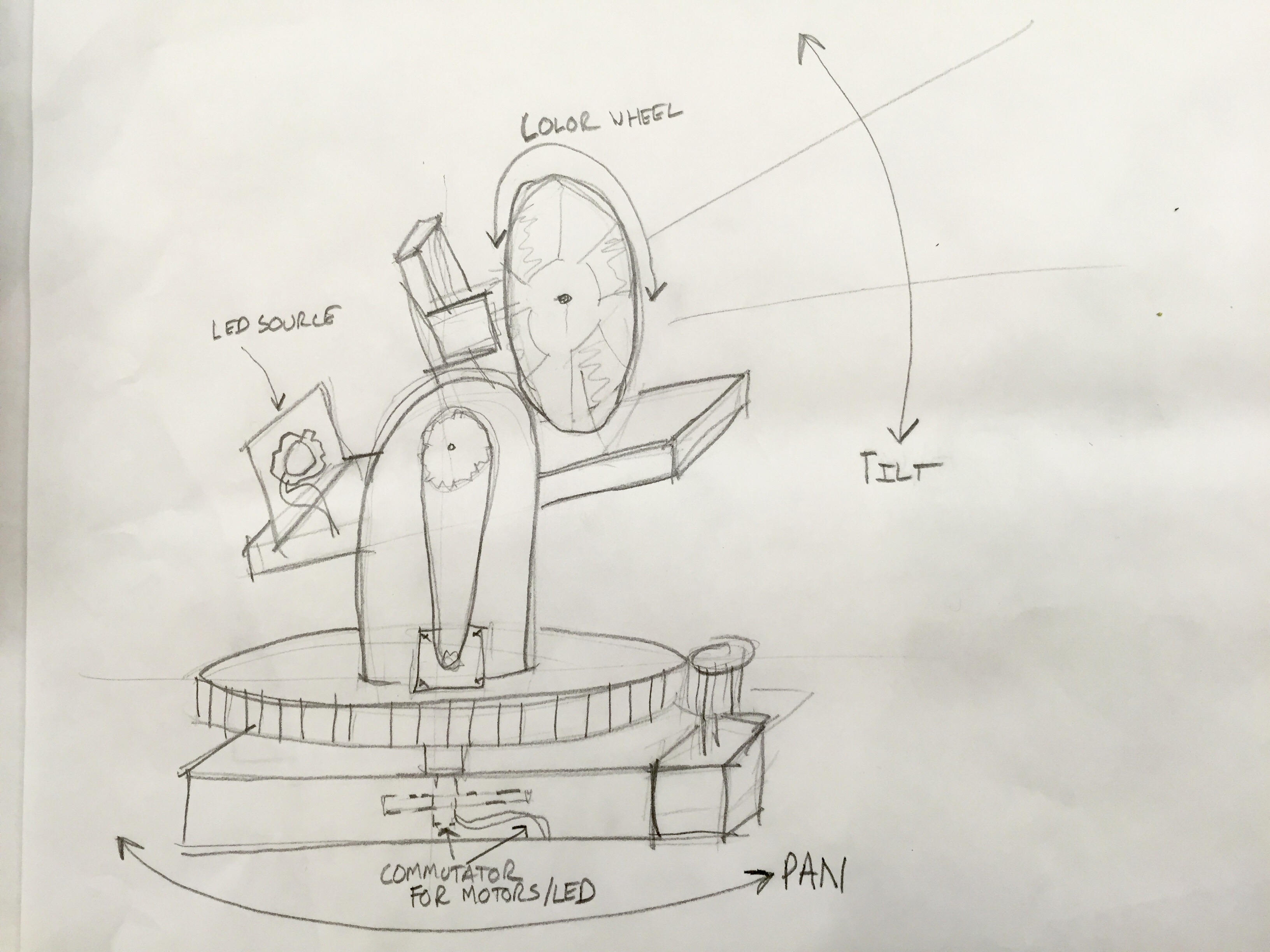
The mechanics will allow and LED source to pan and tilt, And a color / pattern wheel in front of the LED will have colorized flags. I would also like to add a lens that can go back and fourth on a lead screw
The light source will be three or four 3 watt led’s.
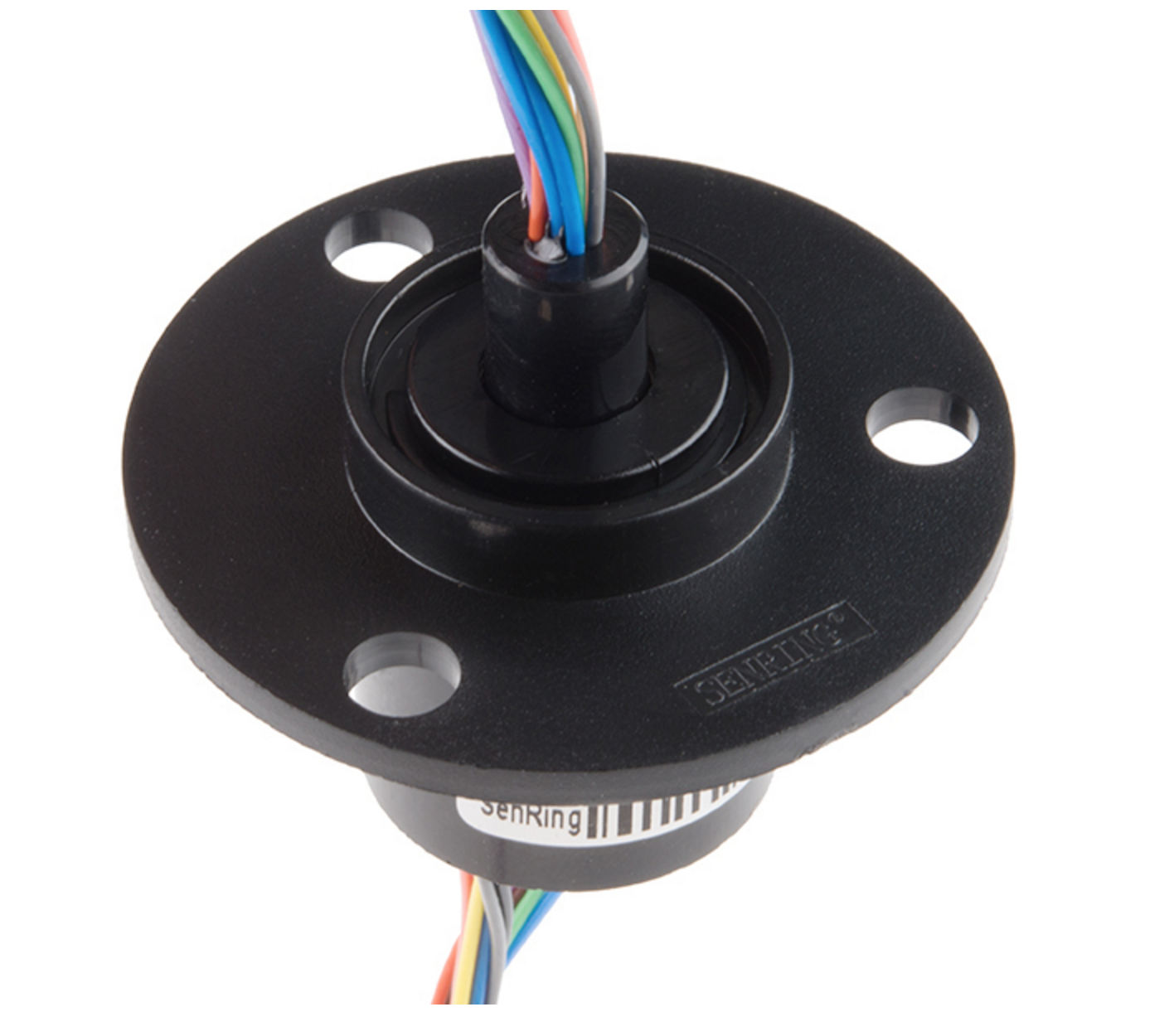
There would be a commutator in the base to get the motor and LED wiring though the 360 degree motion.
Most of the main components I will use will come from robotshop.com. They have a great selection of timing belts, gears, and servo parts.
The rest of my electrode materials have arrived. I have not tried all of them, but I had immediate success with a magnesium rod and two sheets of activated carbon. The battery is drawing 500mA when short circuited!
I attached my new battery to a DC/DC boost circuit and an LED array. Both were taken out of a garden solar light. Most garden solar lights use a single 1.2v NiMh cell, which is nearby to the 1.3V that my battery is producing when the LEDs and boost circuit are connected. To the left you can see how the circuit is pulsing the battery input on my oscilloscope:
The battery will work with many different solutions. Even old wine! (although not as well):
An interesting side effect is that the battery will bubble when a load is applied. I might find a way to incorporate this into the final design.
While I wait for all my electrode materials to arrive, I began my testing of the salt water battery system with what I have available.
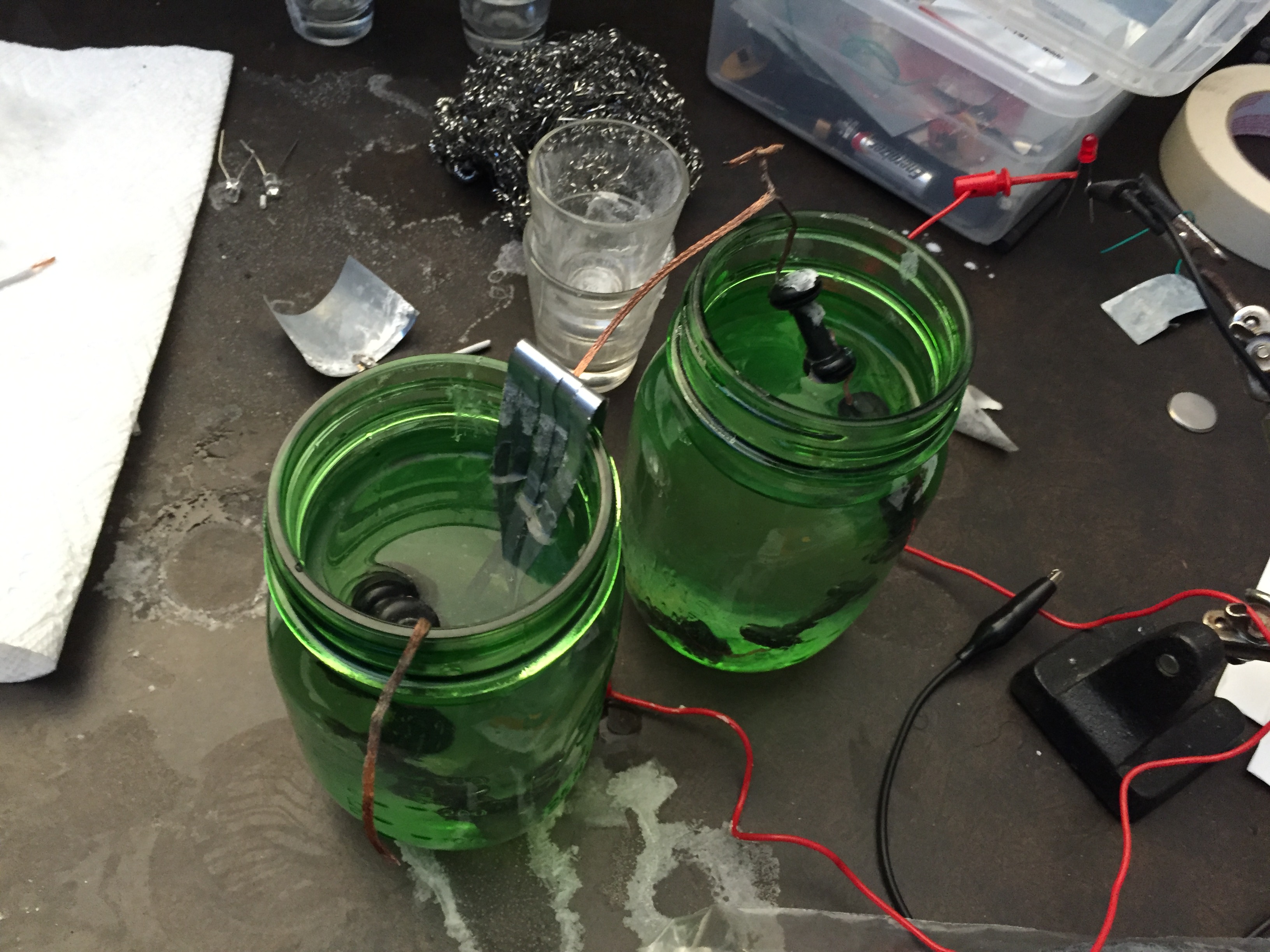
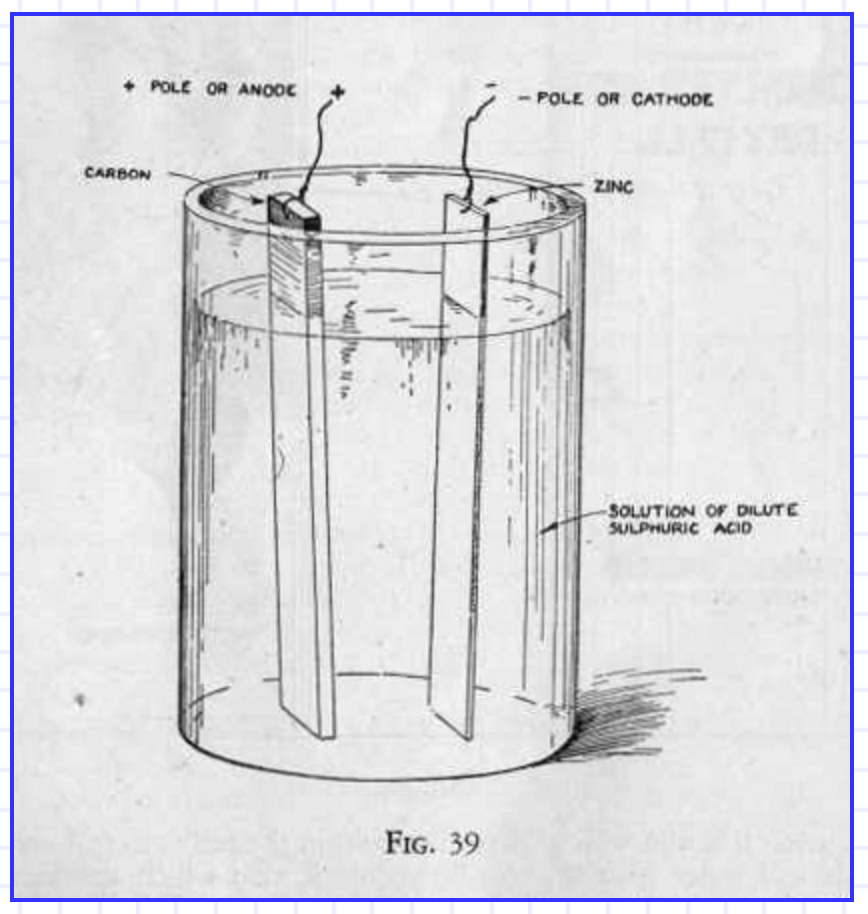
My first test uses a carbon rod and a zinc plate. The result was a very small voltage; even after putting two cells in series this was only enough to light a single red LED:
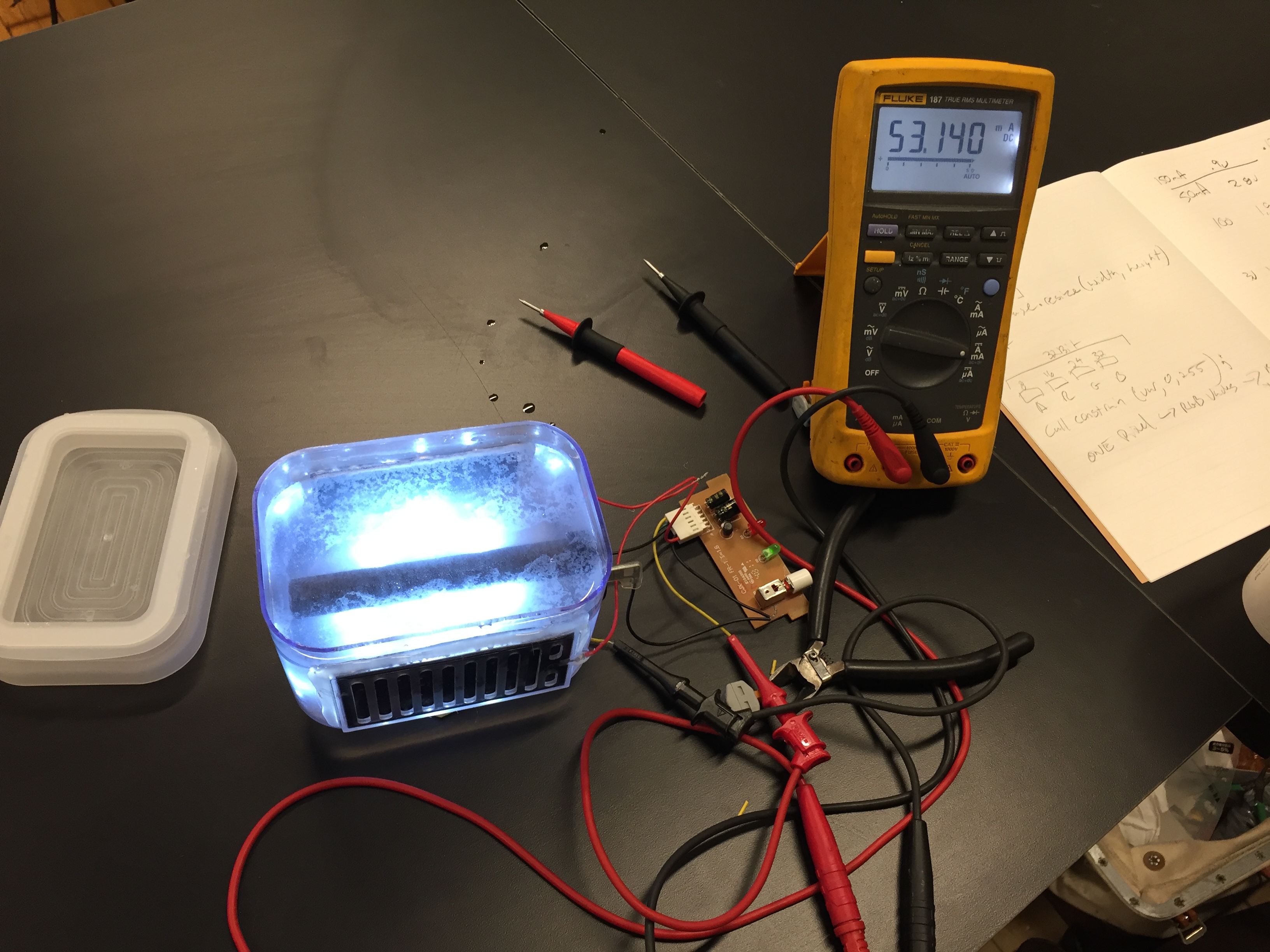
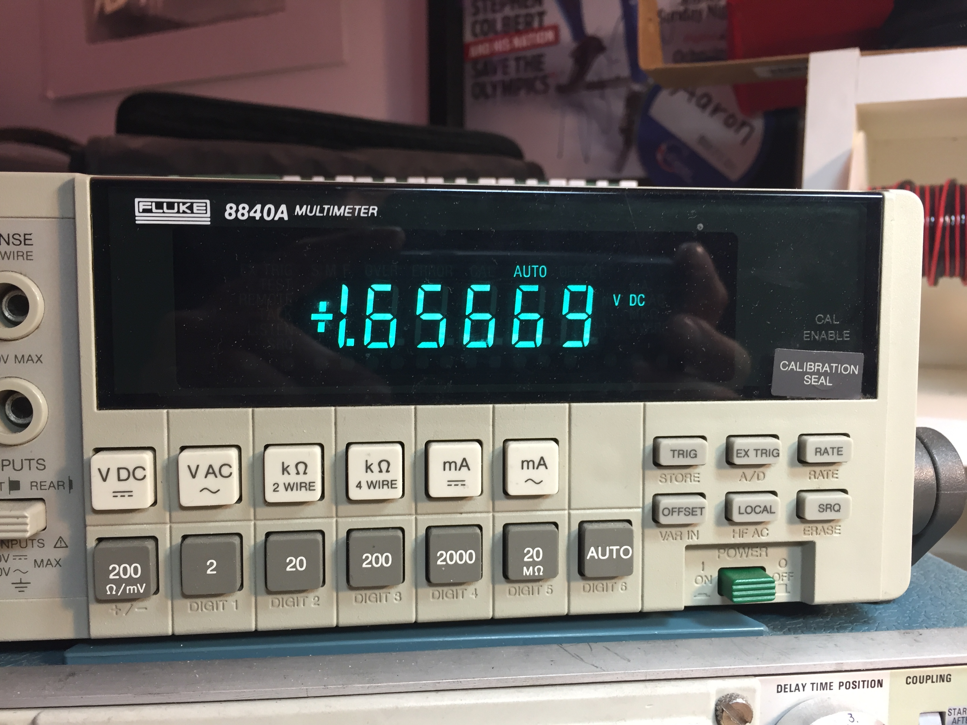
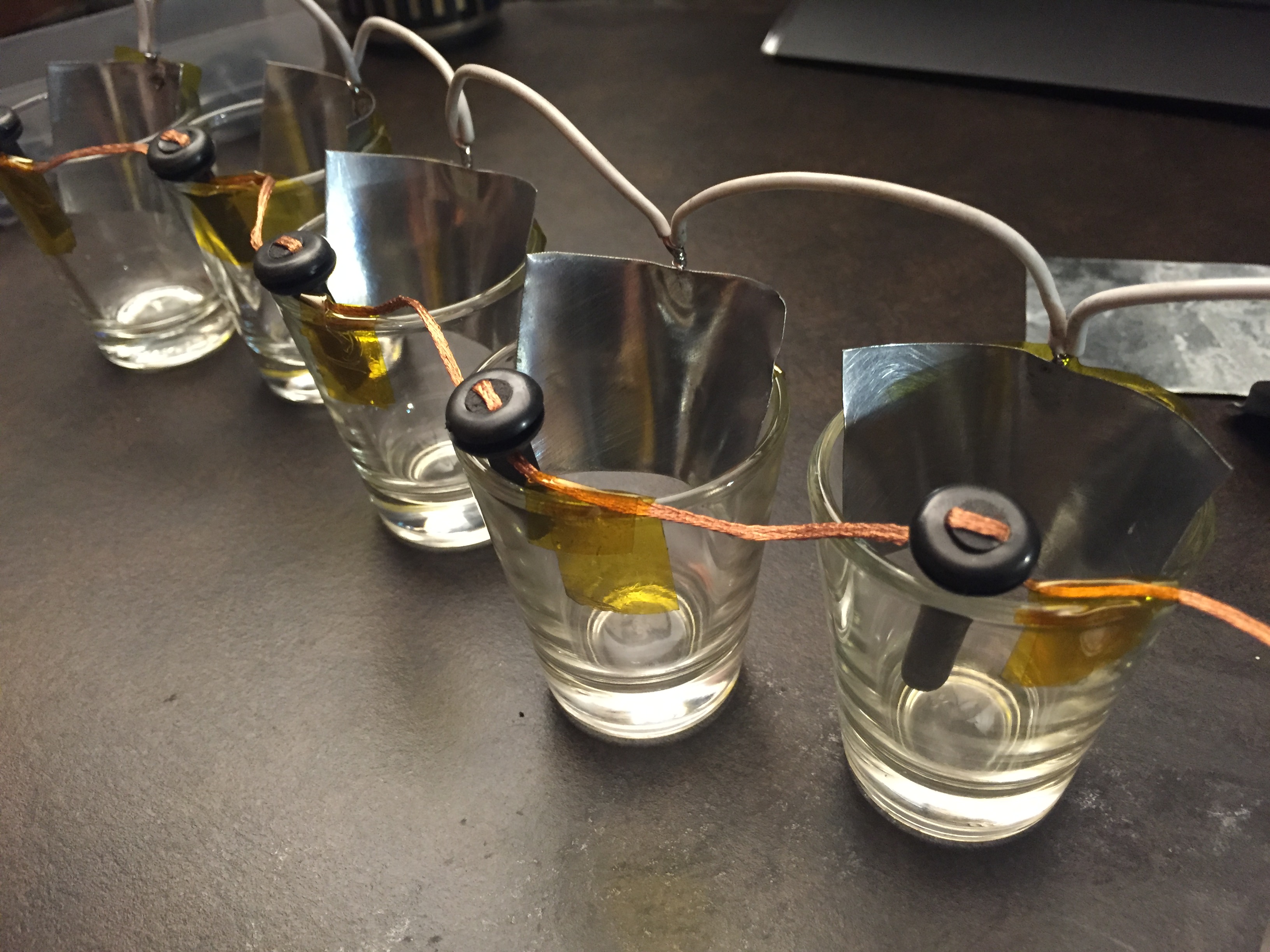
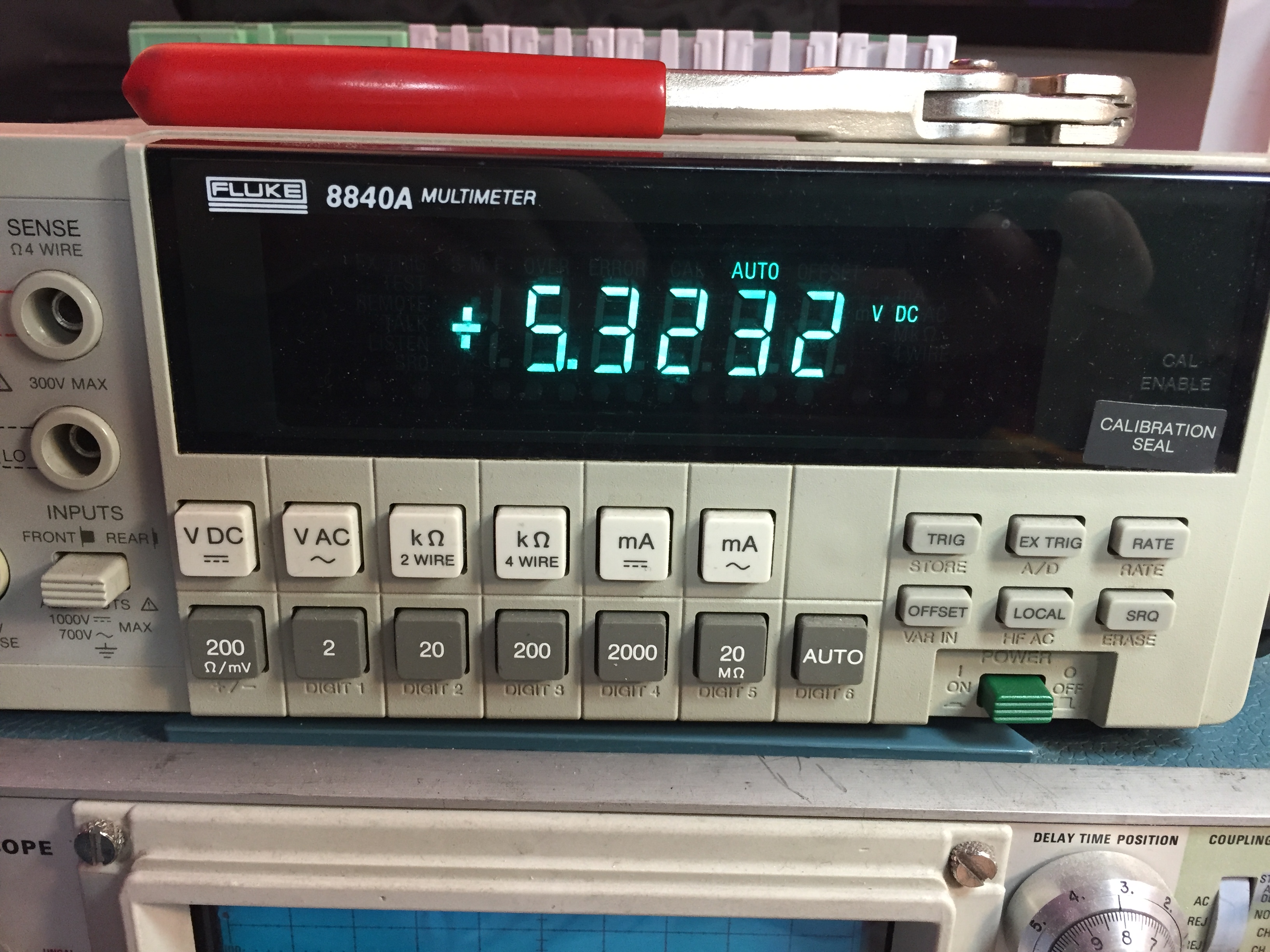
I then tried to increase the voltage by dividing my system into eight cells in series:
This still only provided a few milliamps at 5.3volts
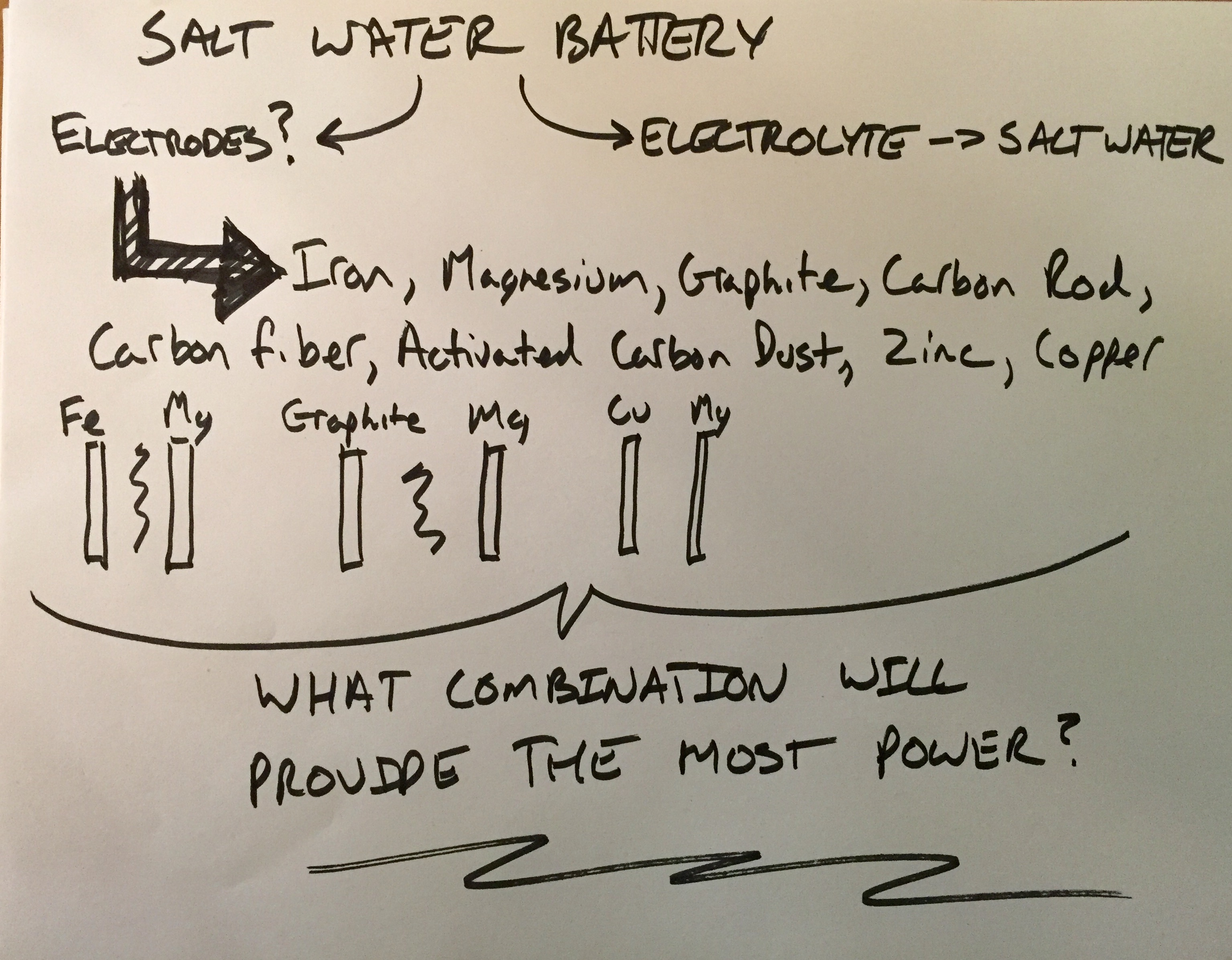
A salt water battery is a wet-cell battery that uses salt water as its electrolyte. Normally wet-cell batteries use acids for their electrolyte. Car batteries use sulfuric acid – nasty stuff. The goal of this project is to to use safer materials than those found in normal batteries. Cadmium, Sulfuric Acid, Potassium hydroxide are all not good for the environment or for people.
My research begins with trying for find out what the two electrodes should be made of to provide the most power out of the saline solution I have chosen. I have decided to work with salt water that has a similar salinity to sea water. I feel using elements and liquids that are commonplace will help people best understand what the battery is made up of. Lead and acids have nasty connotations.
The salinity of seawater according to wikipedia is around 3.5%
Finding information on what the best electrodes to use has proven to be much more difficult to weed through via research on the internet. Let down by hours of weeding through eco-friendly-energy-snake-oil, I decided to order samples of common electrode materials and test them in different combinations myself.
Dream – My dream is to create a personal light that runs via a natural battery and includes a level of interaction that brings with it excitement and enjoyment to its owner. The goal of this light is for it to be an object that comes closer to eco-friendly than its plug-in counterparts. Additionally it should be more than just a utility ‘lantern’ source of light. I like to think of lighting as universal to everyone who can see. I want to design a light that can be used by any person anywhere on the planet.
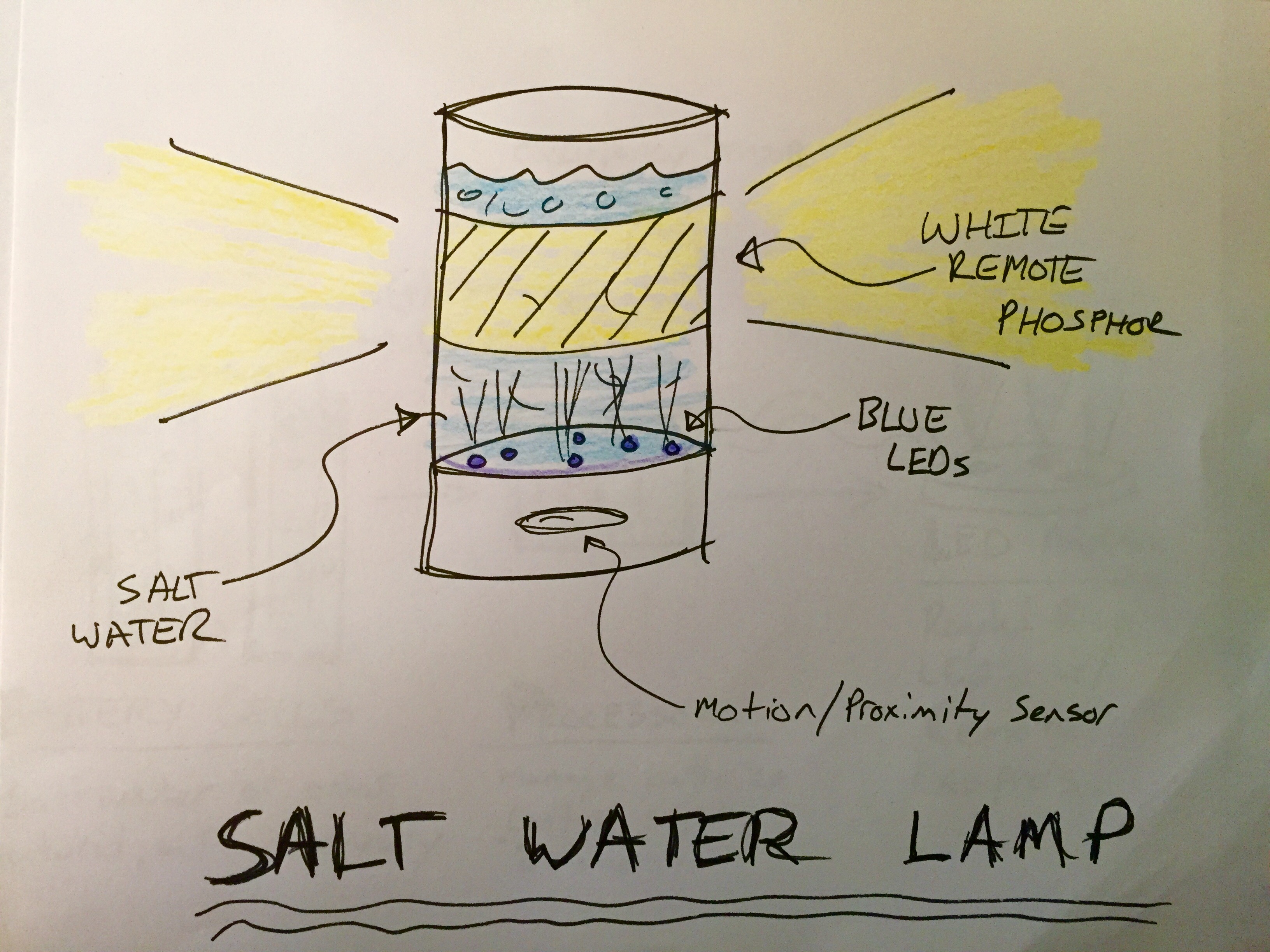
Vision – I would like this light to be powered by an electrochemical source that is less harmful to the environment than typical batteries. A simple salt-water battery or something organic in nature would be ideal. That materials that make up the enclosure should be more eco-friendly than just plastic as well. The light itself should be at least bright enough to allow its owner to read with. I have been experimenting with remote-phosphor LED lighting, and I think using blue LED’s to light a white phosphor plane would be a novel addition to the project.
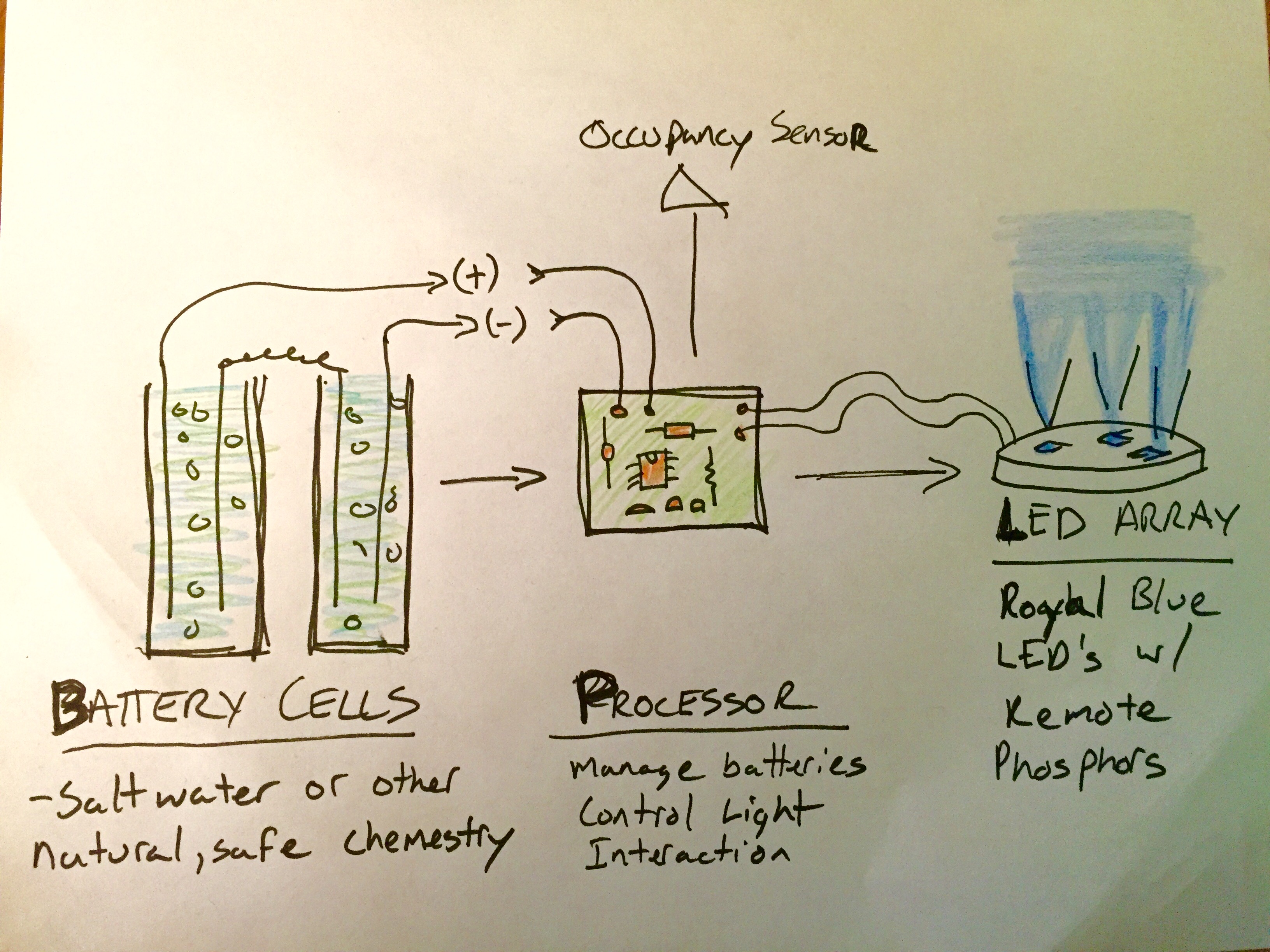
Goal – This semester at ITP I would like to build a working light that operates via an organic battery. The battery will power an LED array as well as a microcontroller that will adapt the output of the LED array in terms of mood and intensity for the user based on readings from a proximity sensor.
Plan – (35% chance things go this way)
2/10 – Research saltwater batteries and useable electrodes
2/17 – Order and test different electrode materials to find the best combination
2/24 – fine tune battery
3/2 – fine tune battery and DC/DC boost circuit, research high efficiency LED’s
3/9 – create LED array, research low energy atmel MCU’s
3/23 – Decide on proximity sensor, proof with chosen MCU
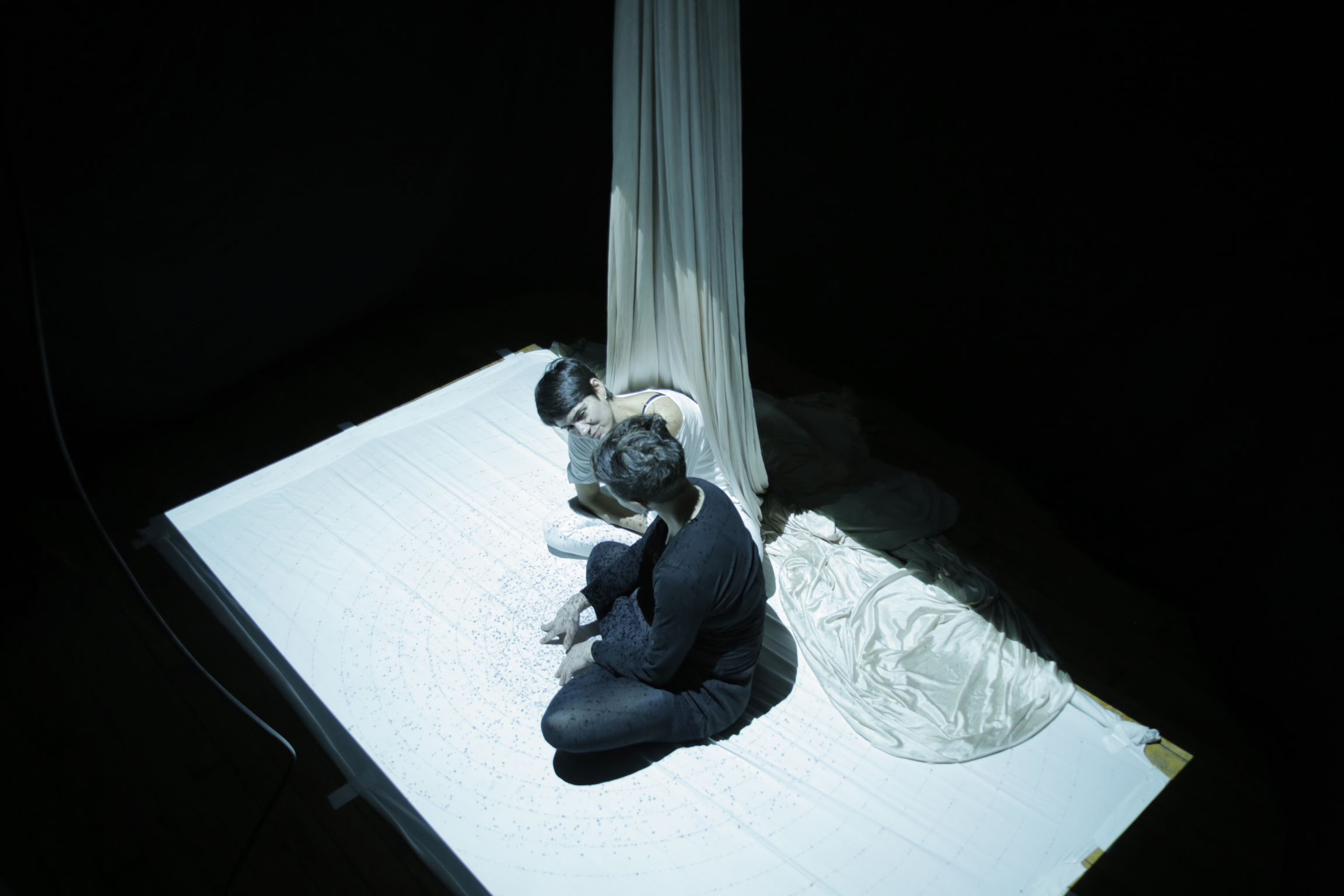
Beats Exposed is an interactive performance experience that breaks down the barrier between audience and performer. By exposing the body’s vital signs, the performer invites the audience to see beyond the polished act and into the extreme physical and personal effort.
Beats Exposed is built to be used in performance on, or off, stage. It is lightweight and able to run in a variety of settings.
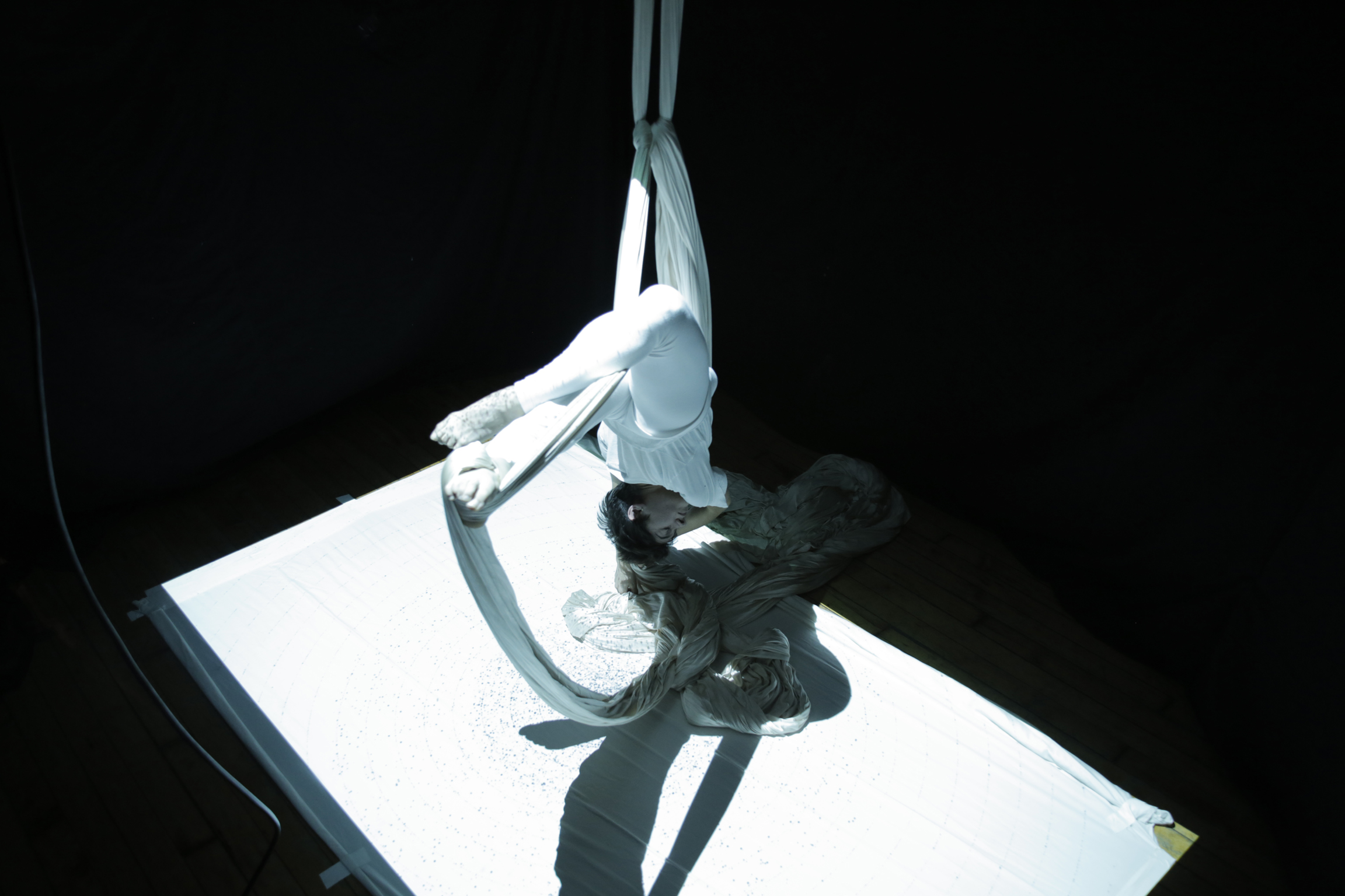
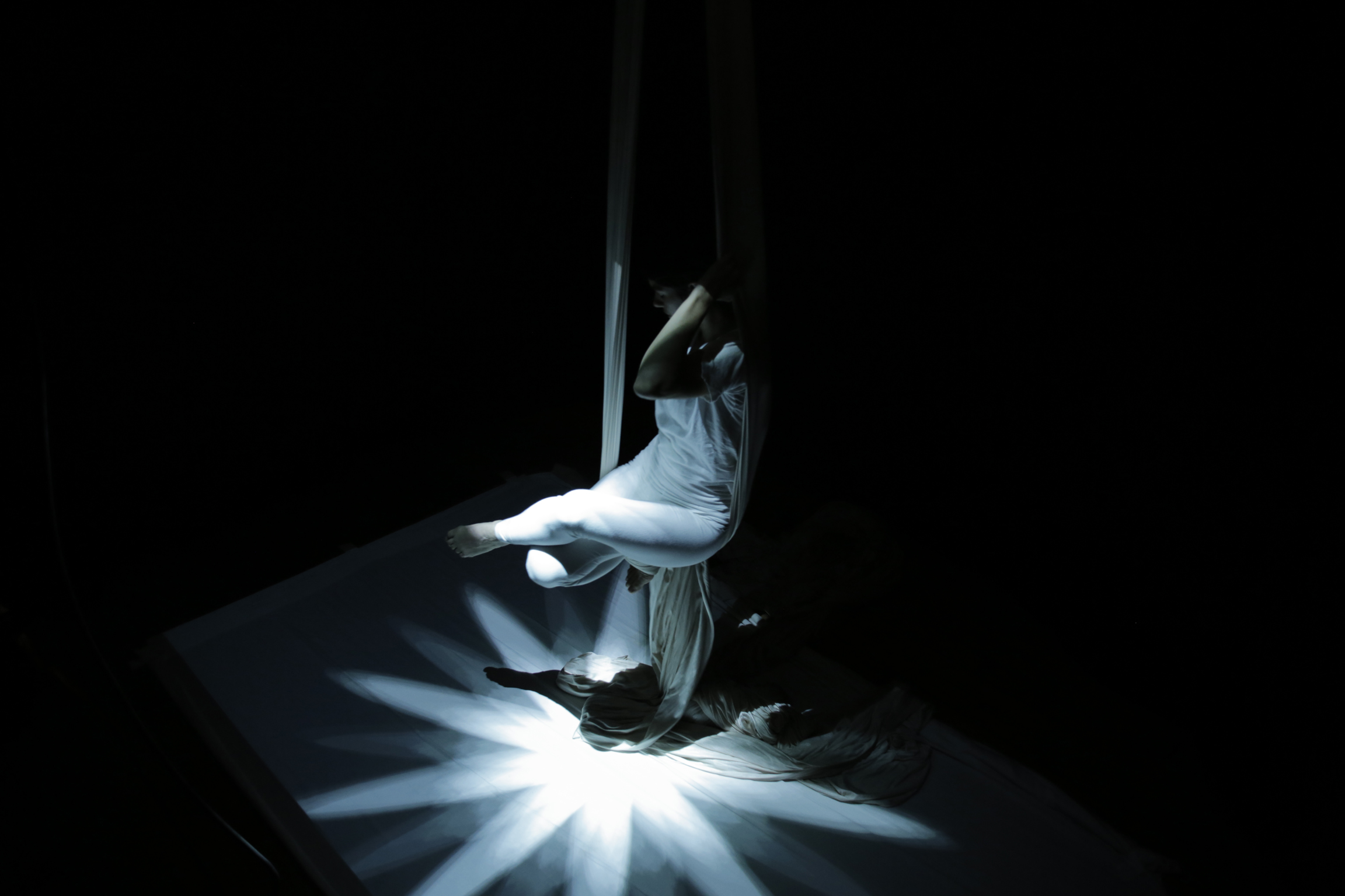
Our current iteration of the project is performed with an aerialist. It exposes the exertion in an artform that is extremely demanding, yet typically meant to appear effortless.
Or project senses the aerial performers heartbeat with a Polar pulse sensor, and sends this pulse wirelessly via two Moteino boards. The pulse is then used in a P5 javascript sketch to effect audio and visualizations.
In this experience, the audience hears the sound of a heartbeat timed with the performer’s pulse. The visualization, also reacting to the pulse, projects from the ceiling onto the performer, surrounding area, and any audience members that have come in close. The resulting experience is intimate, personal and engaging.
The polar band is able to send a reliable heart pulse even during movement
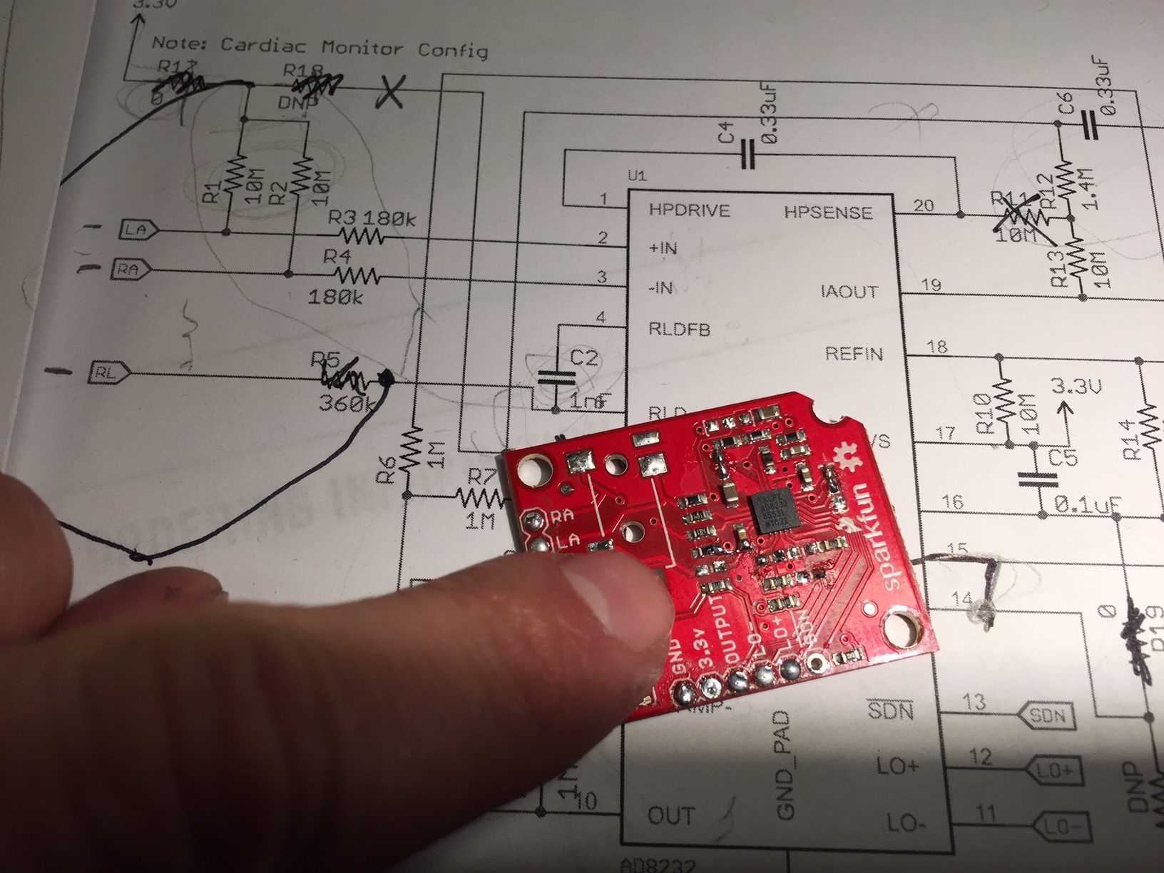
Our method for measuring the heart beat of the performer changed drastically over the course of our testing. The first version we used worked via sticky electrodes attached to the chest and connected to an EKG operational amplifier which amplifies the minute voltages generated by the heart. We quickly ran into noise issues when the performer made any slight movement. After trying some simple signal processing in arduino, as well as modifying our EKG breakout board to include heavy filtering, we found it very hard to get a reliable signal.
After a lot of research into portable EKG units worn by the ‘patient’, I began to learn the importance of using an accelerometer alongside the electrodes in order to filter out movement noise. The first time I heard of such a thing was buried in a youtube video:
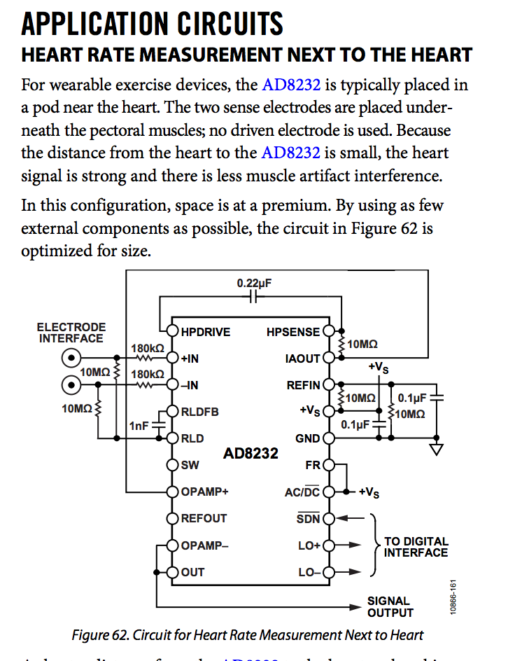
Combining the operational amplifier with an accelerometer via a small microcontroller is also in the datasheet for the heartrate sensor.
Trying to implement this kind of digital signal processing ourselves was quickly starting to look too difficult for a project due in 2 weeks!
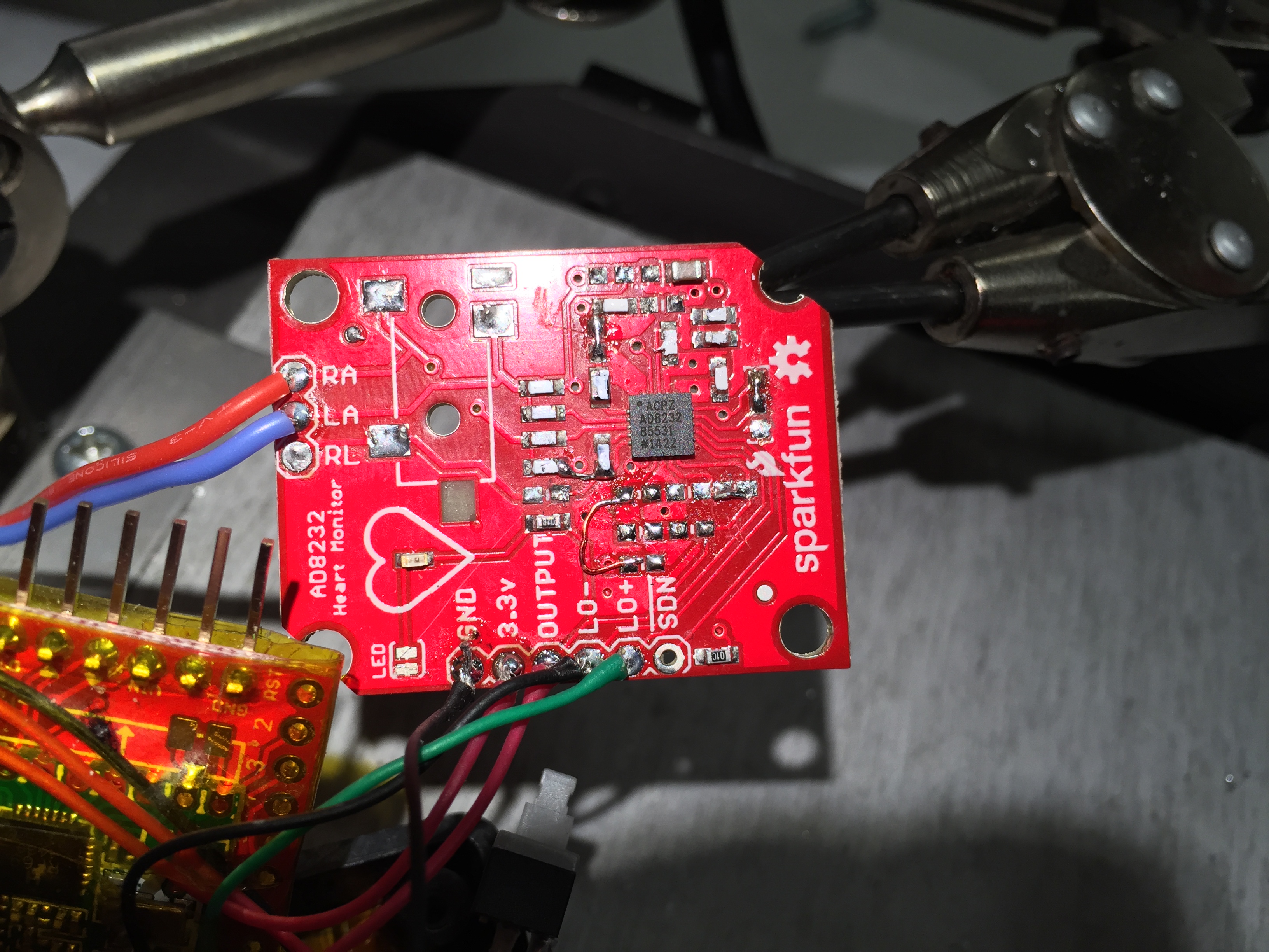
Trying to change around the circuit on the breakout board was a challenge!
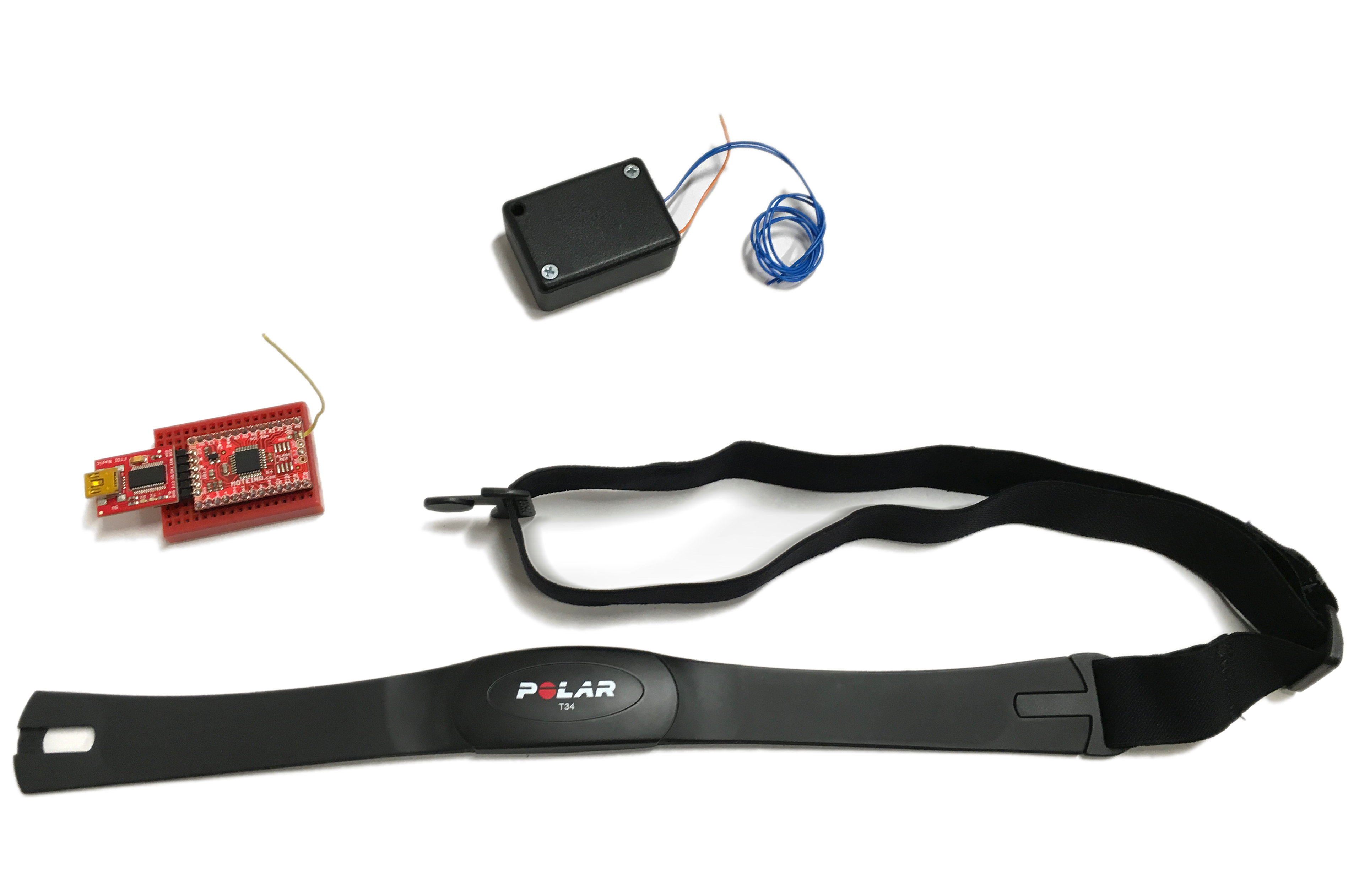
Eventually we found a product–the Polar T34 pulse monitor that handles this processing. By using this band as our sensor, we were able to get a very accurate heartbeat pulse that was free from noise even during movment.
Our final human interface works by receiving a pulse signal from the Polar monitor for every heartbeat, which is then transmitted wirelessly via a Monteino transmitter (over a 915MHz serial bridge) that is worn by the performer. This 915MHz signal is then received by a second Moteino that sends the pulse along to P5 via serial. In order to make sure that P5 sees every pulse, each heart beat is about 320ms long.
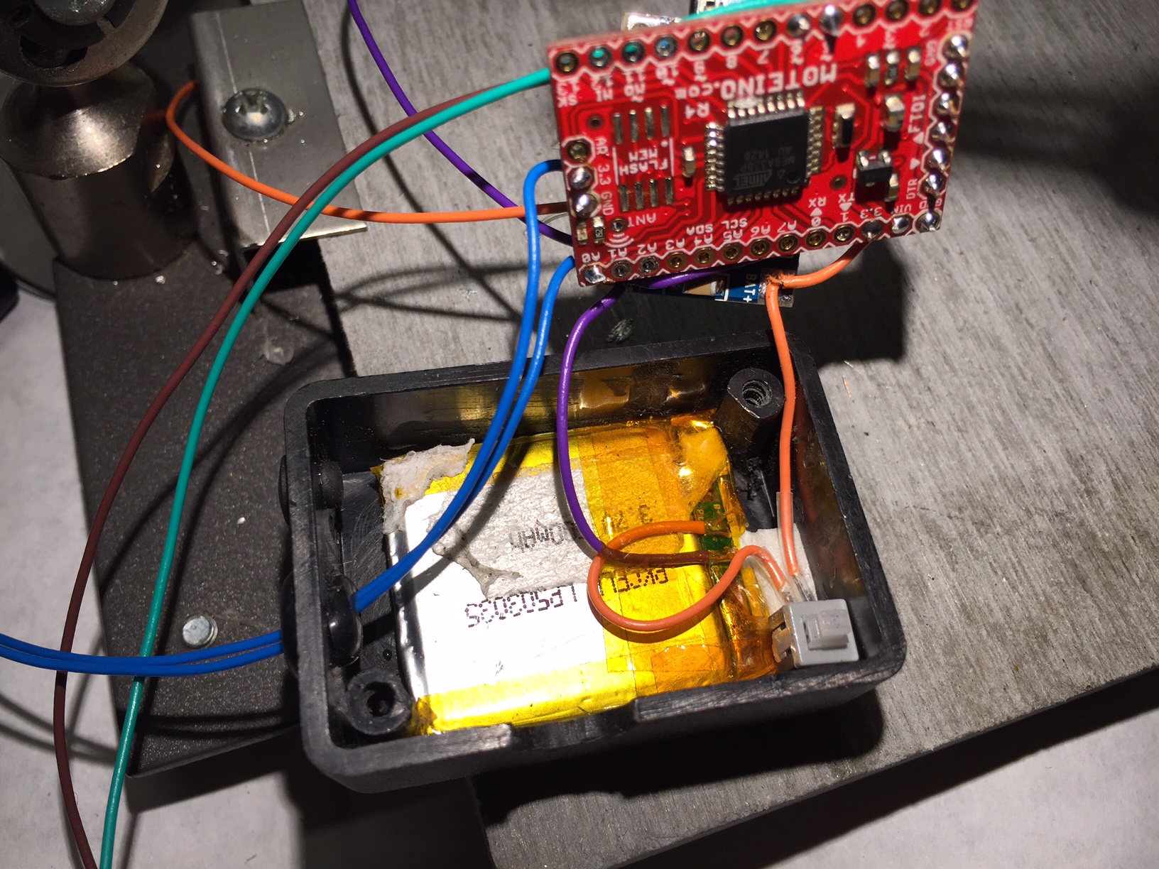
Our project used lots of Kapton tape to insulate between the battery and three circuit boards
Our original proposal included a breath/stretch sensor in addition to the pulse sensor. We thought implementing this would be relatively simple. In reality, the stretch sensor was very sensitive to movement and we were unsuccessful at getting a usable reading.
It took three iterations over about one month to get the pulse sensor working as we intended. We tried an optical pulse sensor, a three electrode EKG heart monitor, and a two electrode heartbeat monitor. All three of these sensors were plagued with electrical noise whenever the performer moved. Finally we arrived at the Polar T34 heartbeat band, which is designed to produce a reliable heartbeat even during times of heavy physical movements. We found this band provided an extremely accurate representation of the performers heartbeat, even when they were moving.
We spent a lot of time working with the the serial communication to get a reliable signal. Once the signal was in P5, we found we had to simplify our sketches significantly in order for them to run reliably. In the future we would likely try to use Processing for visuals.
Our final code for the project can be found on github: https://gist.github.com/lisajamhoury/e8a7de48f8155078efe2
Interestingly, some of our testers had a negative reaction to the sound of the heartbeat played over headphones. We don’t yet understand why some find the sound unbearable, while others find it centering and calming. We will continue to refine the sound and user test to get a better understanding of this sensitivity.
Our final project is coming along great so far. The biggest change we have introduced is switching to the Polar heart band instead of the electrodes and AD8232 heart monitor we started with. We found a second circuit in the data sheet that would filter noise. It was hard to follow tiny traces and components on the sparkfun breakout board.
Even after modifying the the AD8232 breakout board to the heavy noise filtering circuit, we were still unable to get a reliable signal
After extensive research, we learned that in order to monitor the tiny voltages associated with heart rate reliably during movement, we would need an accelerometer to get movement data to process and filter noise from the signal. Luckily a product exists that takes care of a lot of this front-end work already: the Polar heart band!
The polar band is able to send a reliable heart pulse even during movement
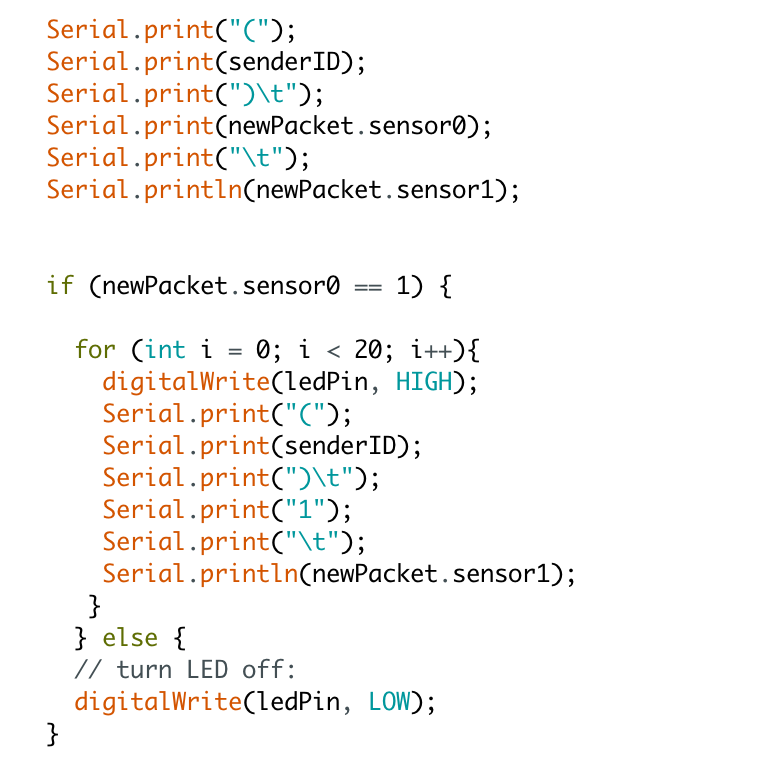
The polar sends a low frequency 16ms pulse for every heartbeat. We receive this with a proprietary polar receiver, which then pulls an input pin high on the wearable moteino for every beat.
This beat happens a little fast for p5, so we increase its duration to 320ms before outputting it to serial:
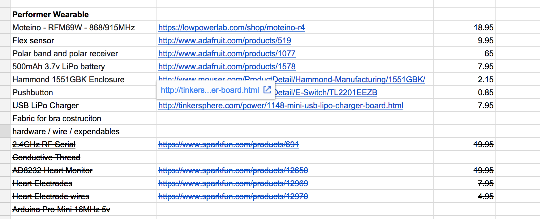
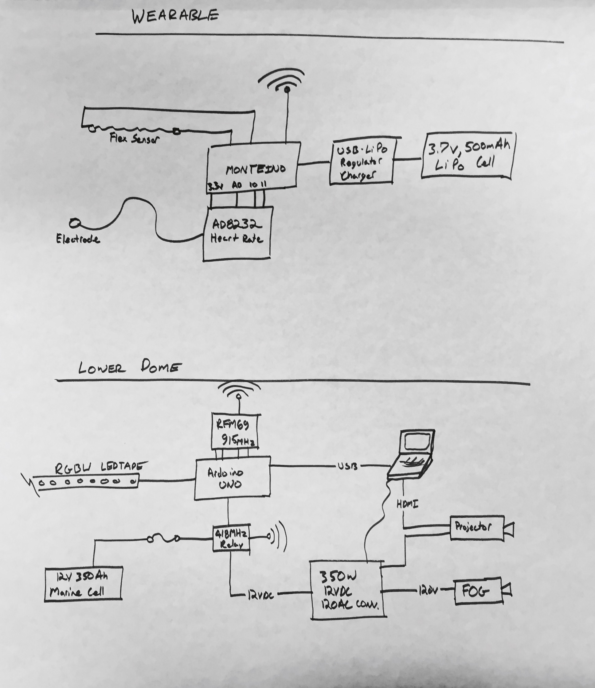
This week we honed in our Bill of Materials and riser diagram for our final. For the wireless serial aspect of our project we are using the RFM69 chipset at 915MHz.
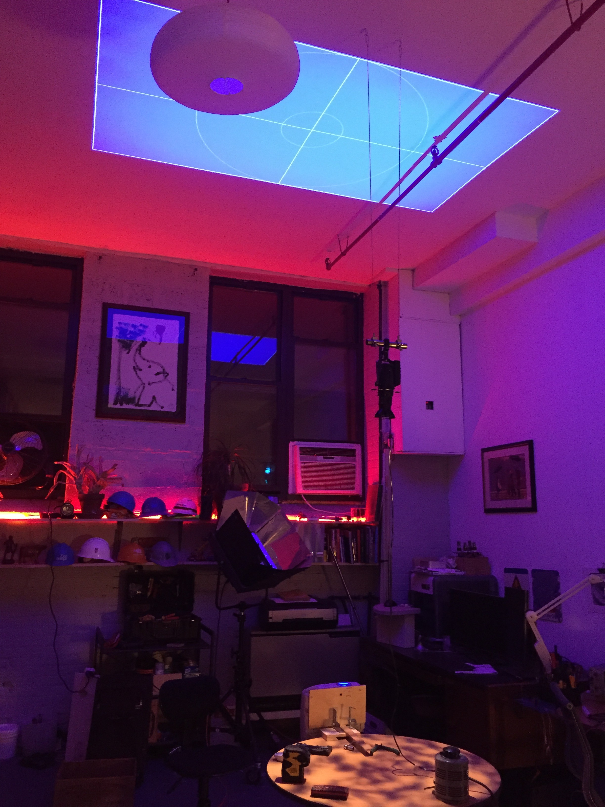
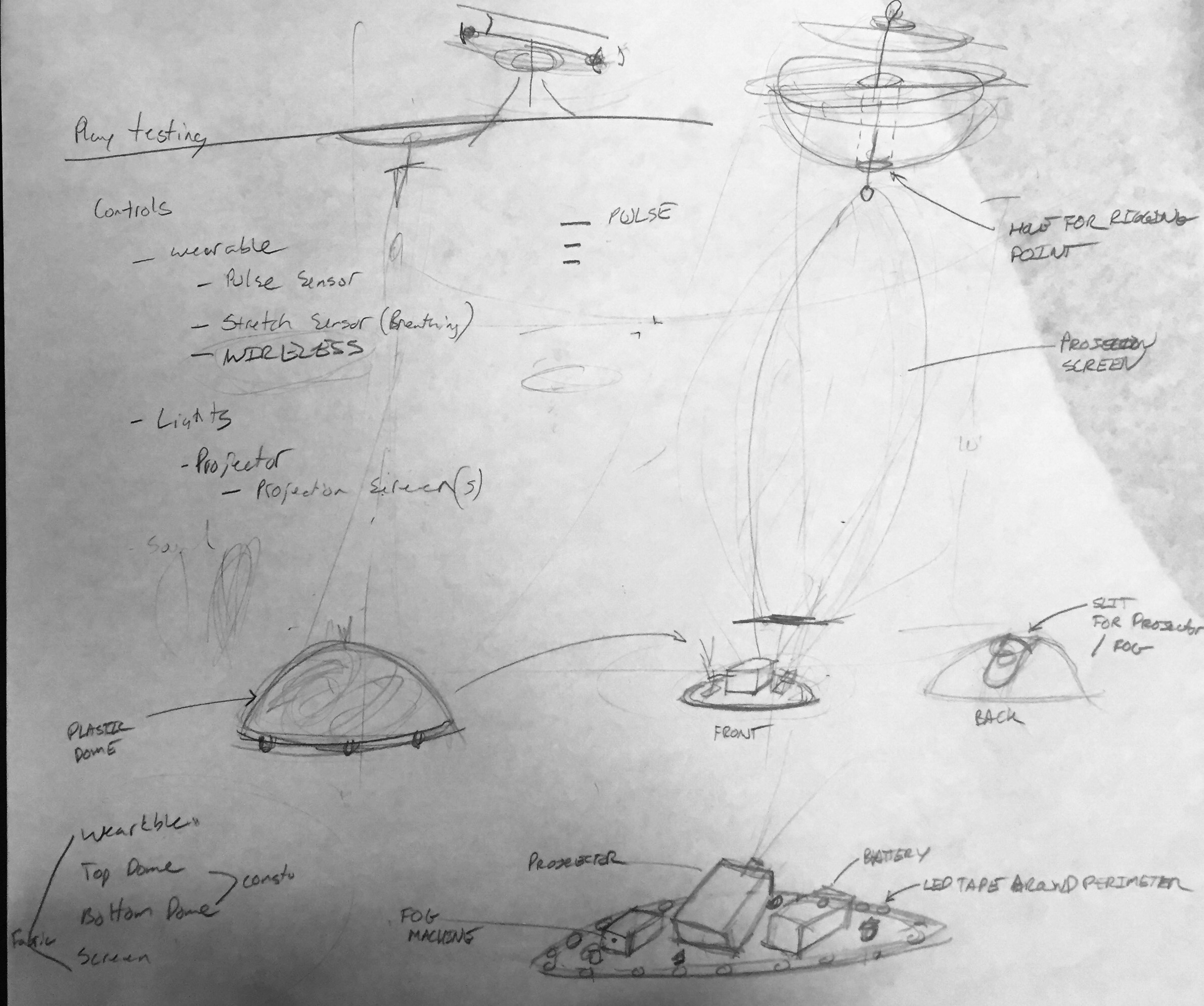
We decided to eliminate the upper dome and just go with the bottom one. Currently I am experimenting with mounting the projector in the ceiling vs. in the dome with a mirror in the ceiling. Either way our new goal is for the projections to be on the floor.
Messing with projectors and mirror squares in my apartment:
We moved ahead with our stop motion animation using Karl the lego construction man.
The process was very time consuming, but I enjoyed it and I felt the three of us (Katy, Mathura and myself) all worked very equally on it. From setting up to editing the process took us 12 hours for a 49 second video!
The music was taken from chips challenge, an old computer game:
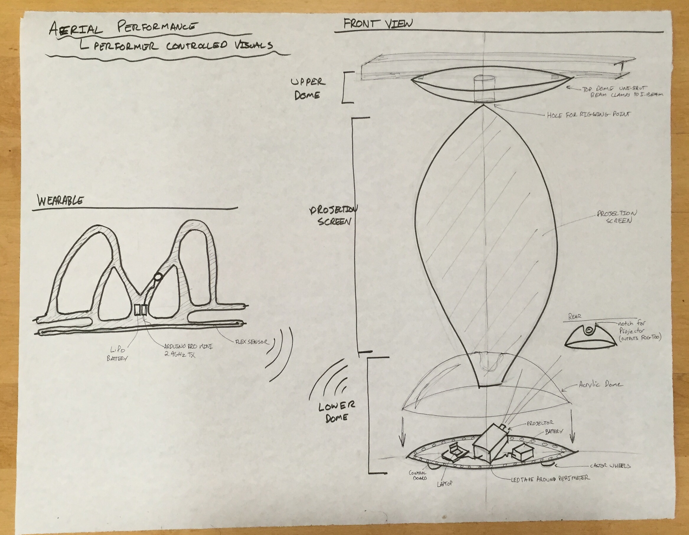
The key ingredient in performance art of any kind is the human performer. For our Physical Computing final, Lisa Jamhoury and myself, and Danielle Butler would like to use electrical sensors and computational media to better translate the action and emotion of a performer to his or her audience. For this project the focus is for an aerial performance. We would like to draw an audience closer to an aerial performer, and to do so outside the confides of a traditional performance space. To meet these goals we will create a portable device that will take inputs from the human performer and translate them to lighting and projected visuals.
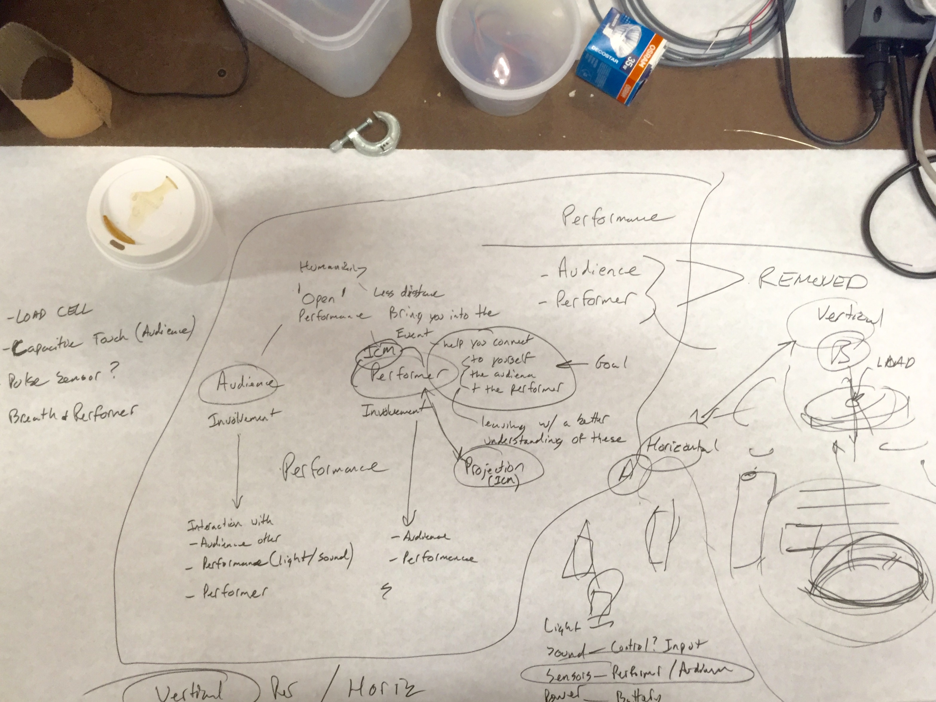
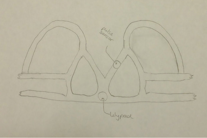
some of our original sketches:
One main priority is to only use physical inputs that will produce definite translations. I think using inputs that we can fully count on and coding them work as fluid as possible is key. (I’m not sold on the xbox kinect).
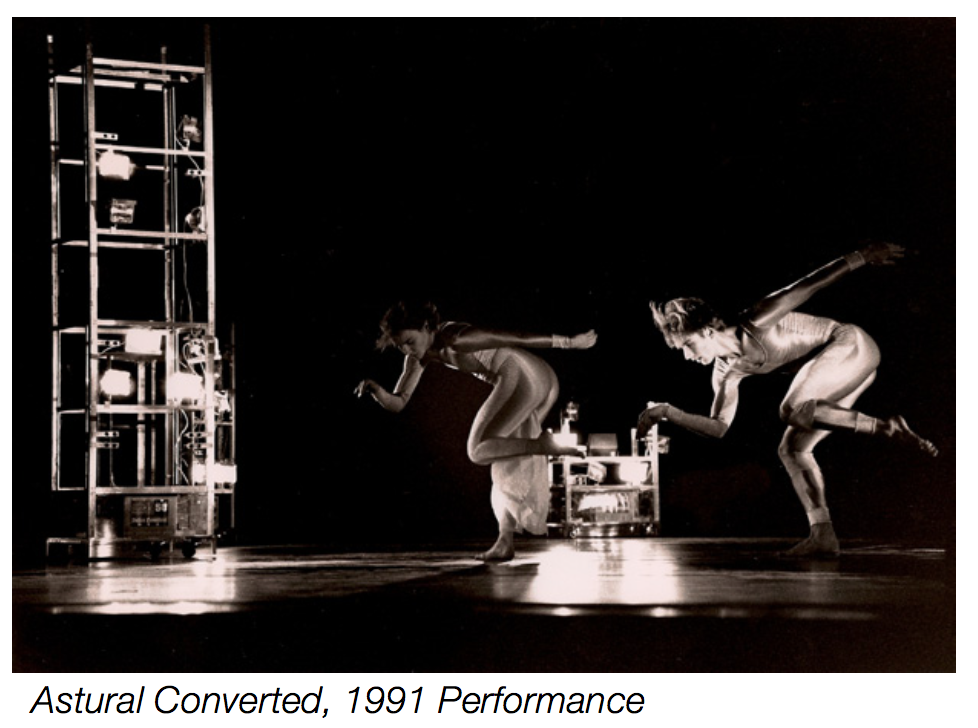
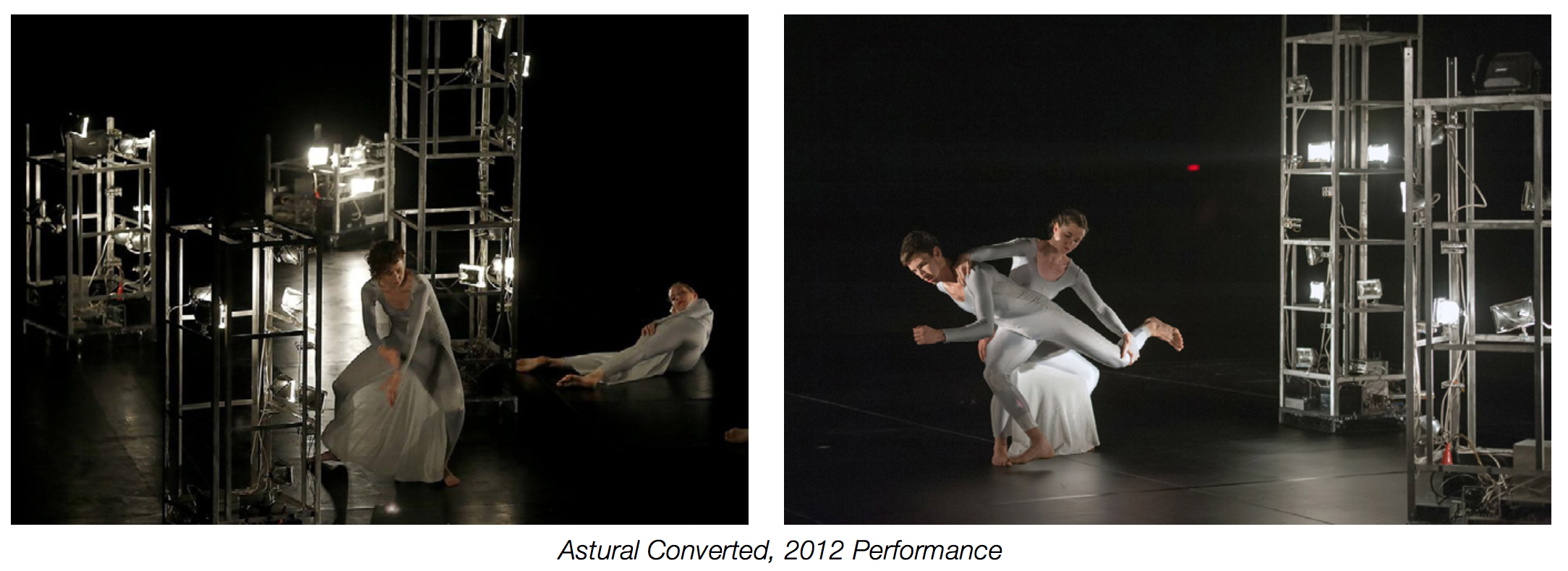
The basis of my idea of interacting with the performer comes from my work restoring a sculpture designed by Robert Rauschenberg. In 2012, I was asked by Trisha Brown Dance Company to restore the electronic set pieces for Astural Converted. The set was composed of eight wireless, aluminum framed towers. Each contains light sensor activated sound and lighting. Designed by Robert Rauschenberg in 1989 and constructed by engineers from Bell Laboratories, the towers turn off and on their lamps based on the performers movements. Each tower also plays a different part of the musical score via individual tape decks. .
Im excited about taking this idea of car headlights and tape decks controlled by a dancers movement, and scaling it up to and digital sensors and stronger visuals.
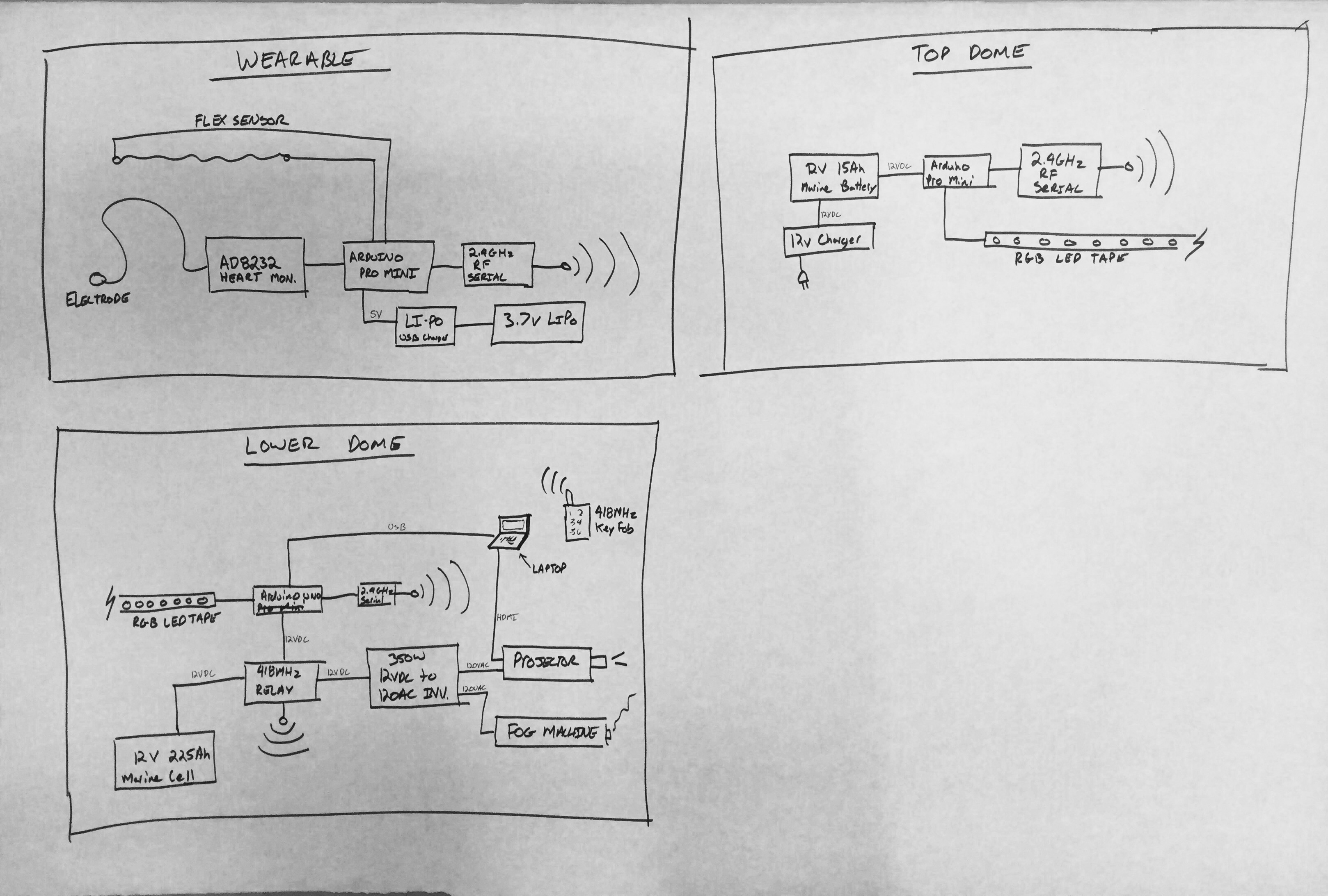
Here is our initial block diagram:
Our project will take a stretch sensor and heart rate sensor from a performer, and translate them to RGBW LED strips and projected images running from a p5 sketch.


